
Manual

DS-3D2208P Hardware Installation
Manual
- 12 -
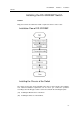
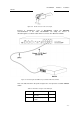
Note: The switch shown in the previous figure does not represent a real DS-3D2208P
switch.
Table 0-1 Definition of the pins of the UTP port
No.
Name
Symbol
Remarks
1
Carrier Detecting
CD
No connect
2
Data receiving
RXD
Input
3
Data-line device ready
DSR
No connect
4
Data transmitting
TXD
Output
5
Transmission requesting
RTS
No connect
6
Response transmitting
CTS
No connect
7
Data terminal ready
DTR
No connect
8
Signal ground
SG
GND
Note:
The console port of the DS-3D2208P switch does not support traffic control. Therefore,
you must set the option
data traffic control
to
none
when you configure the switch
with the super terminal. Otherwise, the single-pass problem will arise on the super
terminal.
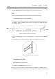
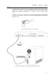
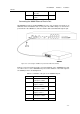
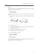
Otherwise, the single-pass problem will arise on the super terminal. The cable is used
to connect the console port of the DS-3D2208P switch and the outside console
terminal device. One end of the cable is a 8-pin RJ45 plug and the other end is a
9-hole plug (DB9). The RJ45 plug is put into the socket of the console port on the
DS-3D2208P switch. The inner line connection in the cable is shown in figure 3-1. The
console cable is numbered as RLC0301.
Figure 0-5 Cable connection at the console port
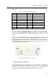
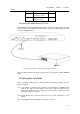
Connecting Ethernet 100M Port
The DS-3D2208P switch has 8 10/100Base-T ports. The LEDs are labeled with
numbers 1-8, indicating the link/ACT state of the port. You can connect other Ethernet
terminal devices to the UTP port through the cut-through or cross network cable. The
numbering order of the pins in the UTP port is the same as the console port.