Quick Start Guide
Manuals
Brands
Hikvision Manuals
Mobile Network Cameras
Mobile DeepinView Separated Network Camera
31
32
33
34
35
36
37
38
39
40
Table Of Contents
1 Appearance Description
1.1 General Appearance
1.1.1 Type I Camera General Appearance
1.1.2 Type II Camera General Appearance
1.1.3 Type III Camera General Appearance
1.2 Front Panel
1.2.1 Type I Covert Camera Front Panel
1.2.2 Type II Covert Camera Front Panel
1.2.3 Type III Covert Camera Front Panel
1.3 Rear Panel
1.3.1 Type I Covert Camera Rear Panel
1.3.2 Type II Covert Camera Rear Panel
1.3.3 Type III Covert Camera Rear Panel
1.4 Sensor Units
2 Installation
2.1 Installing the Main Unit
2.1.1 Installing Type I Covert Camera Unit
2.1.2 Installing Type II Covert Camera Unit
2.1.3 Installing Type III Covert Camera Unit
2.2 Installing the Block-Shaped Sensor Unit
2.2.1 Concealed Mounting
2.2.2 Exposed Mounting
2.2.3 Mounting with Pole-Shaped Bracket
2.3 Installing the Cylindrical Sensor Unit
2.4 Installing the Tube Lens
2.5 Installing the Ball-Shaped Sensor Unit
2.5.1 Mounting with the Included Bracket
2.5.2 Mounting with a Incline Bracket
3 Activate and Access Network Camera
Network
Co
vert Camera
·
Quick Start Guide
39
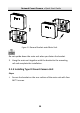
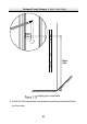
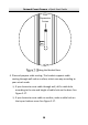
1.83m
(6ft)
Cable
Holes
Cable
Hole
Route cable through wall
Route cable on surface
Plan Cable Routing
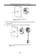
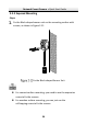
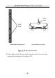
5.
Route cable and fit the lens bracket int
o the base. Use a sc
r
ew to
secure the lens brack
e
t
.
S
ee
Figure 2
-
18
.
1
...
...
38
39
40
41
42
...
...
59