DS-2TD2xxx-xx/xx Thermal and Optical Bi-Spectrum Network Bullet Camera Quick Start Guide
DS-2TD2xxx-xx/xx Thermal and Optical Bi-Spectrum Network Bullet Camera Quick Start Guide © 2020 Hangzhou Hikvision Digital Technology Co., Ltd. All rights reserved. This Manual is the property of Hangzhou Hikvision Digital Technology Co., Ltd., or its affiliates (hereinafter referred to as “Hikvision”), and it cannot be reproduced, changed, translated, or distributed, partially or wholly, by any means, without the prior written permission of Hikvision.
DS-2TD2xxx-xx/xx Thermal and Optical Bi-Spectrum Network Bullet Camera Quick Start Guide Regulatory Information FCC Information Please take attention that changes or modification not expressly approved by the party responsible for compliance could void the user’s authority to operate the equipment. FCC Compliance This equipment has been tested and found to comply with the limits for Class A device, pursuant to part 15 of the FCC Rules.
DS-2TD2xxx-xx/xx Thermal and Optical Bi-Spectrum Network Bullet Camera Quick Start Guide Symbol Convention The symbols that may be found in this document are defined as follows. Symbol WARNING DANGER Description Provides additional information to emphasize or supplement important points of the main text. Indicates a potentially hazardous situation, which if not avoided, could result in equipment damage, data loss, performance degradation, or unexpected results.
DS-2TD2xxx-xx/xx Thermal and Optical Bi-Spectrum Network Bullet Camera Quick Start Guide Power Supply • • • Make sure that the power has been disconnected before you wire, install, or disassemble the device. Input voltage should meet both the SELV (Safety Extra Low Voltage) and the Limited Power Source with 12 VDC, 24 VAC , or PoE (802.3af) according to the IEC60950-1 standard. Please refer to technical specifications for detailed information. Use a power adapter provided by a qualified manufacturer.
DS-2TD2xxx-xx/xx Thermal and Optical Bi-Spectrum Network Bullet Camera Quick Start Guide Environment • DO NOT expose the device to extremely hot, cold, dusty, corrosive, saline-alkali, or damp environments. Make sure the running environment meets the requirement of the device. The operating temperature shall be -40° to 65° C (-40° to 149° F). • DO NOT aim the lens at the sun or any other bright light. • Keep the camera away from liquid while in use.
DS-2TD2xxx-xx/xx Thermal and Optical Bi-Spectrum Network Bullet Camera Quick Start Guide Table of Contents Appearance Description ................................................................................................................................ 8 Type I Camera Appearance ........................................................................................................................... 8 Type II Camera Appearance .........................................................................
DS-2TD2xxx-xx/xx Thermal and Optical Bi-Spectrum Network Bullet Camera Quick Start Guide Appearance Description There are four thermal and optical bi-spectrum network bullet camera types. Here are overviews of Type I cameras, Type II cameras, Type III cameras, and Type IV cameras.
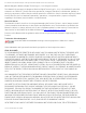
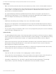
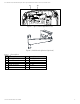
DS-2TD2xxx-xx/xx Thermal and Optical Bi-Spectrum Network Bullet Camera Quick Start Guide 11 10 Figure 3, Type I Camera Appearance (2) Figure 4, Wall Mounting Bracket (Optional) Description No. Description 1 Photoresister 3 Lens (Thermal) 5 Network Cable 7 Alarm Interface 9 Audio Interface 11 Reset QSG DS-2TD2xxx-xx/xx 071720NA No.
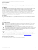
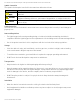
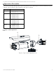
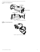
DS-2TD2xxx-xx/xx Thermal and Optical Bi-Spectrum Network Bullet Camera Quick Start Guide Type II Camera Appearance Mount Sun Shield Thermal Lens Memory Card Optical Lens Figure 5, Type II Camera Appearance Type III Camera Appearance Figure 6, Type III Camera Appearance QSG DS-2TD2xxx-xx/xx 071720NA 10
DS-2TD2xxx-xx/xx Thermal and Optical Bi-Spectrum Network Bullet Camera Quick Start Guide Sun Shield Camera Memory Card Slot Bracket Holder Cable Outlet Bracket Hinge Bracket Arm Junction Box Cover Reset Button Junction Box Base Sealing Interface Figure 7, Type III Camera Cables Type IV Camera Appearance Bracket Sun Shield Speaker Reset Button Memory Card Slot Thermal Lens White Light Lamp Optical Lens Figure 8, Type IV Camera Appearance Cable Description The bullet camera cables, including power
DS-2TD2xxx-xx/xx Thermal and Optical Bi-Spectrum Network Bullet Camera Quick Start Guide Audio Output Interface Audio Input Interface Alarm Interface 1 Alarm Interface 2 RS-485 Interface Power Interface (12 VDC) Network Interface Audio Output Interface Audio Input Interface Alarm Interface 1 Alarm Interface 2 RS-485 Interface Power Interface (12 VDC or 24 VAC) Network Interface Figure 9, Cable Description Cable Description Name Description For 12 VDC or 24 VAC power supply, make sure that the positive/neg
DS-2TD2xxx-xx/xx Thermal and Optical Bi-Spectrum Network Bullet Camera Quick Start Guide The junction box differs by camera model. Alarm Interface Audio Input& Output Interface Network Interface Power Interface Figure 10, Interface Description Installation Before You Start • • Make sure the device in the package is in good condition and all the assembly parts are included. The standard power supply is 12 VDC, 24 VAC, or PoE (802.3af). Make sure your power supply matches your camera.
DS-2TD2xxx-xx/xx Thermal and Optical Bi-Spectrum Network Bullet Camera Quick Start Guide Install Memory Card Install Type I Camera Memory Card 1. Unscrew and remove the sun shield. Screws Sun Shield Figure 11, Remove Sun Shield 2. Unscrew and remove the back cover.
DS-2TD2xxx-xx/xx Thermal and Optical Bi-Spectrum Network Bullet Camera Quick Start Guide Figure 12, Remove Back Cover Case 3. Insert a microSD card into the microSD card slot. Figure 13, Insert MicroSD Card 4. Fix the sun shield and back cover to the camera body with the removed screws.
DS-2TD2xxx-xx/xx Thermal and Optical Bi-Spectrum Network Bullet Camera Quick Start Guide Install Type II and Type IV Camera Memory Card Type II and Type IV camera memory cards are installed in the same way. Here is an example of memory card installation for a Type II camera. 1. Unscrew and remove the memory card slot cover. Figure 15, Remove Card Slot Cover 2. Insert a microSD card into the microSD card slot until the card clicks. Figure 16, Insert MicroSD Card 3.
DS-2TD2xxx-xx/xx Thermal and Optical Bi-Spectrum Network Bullet Camera Quick Start Guide SD CARD Memory Card Cover Figure 17, Remove Card Slot Cover 2. Insert the memory card into the memory card slot. Memory Card Figure 18, Insert Memory Card 3. Cover the memory card slot and fix the screws on the memory card slot cover.
DS-2TD2xxx-xx/xx Thermal and Optical Bi-Spectrum Network Bullet Camera Quick Start Guide • Detect Target: The target should be at least 1.5 pixels on the image. • Recognize Target: The target should be at least 6 pixels on the image. • Identify Target: The target should be at least 12 pixels on the image. This table is for reference only, and the actual detection range may vary due to camera settings, mounting condition, monitor, etc. Install Camera 2.3.1 Install Type I Camera 1.
DS-2TD2xxx-xx/xx Thermal and Optical Bi-Spectrum Network Bullet Camera Quick Start Guide Figure 21, Fix the Camera to the Wall 4. Adjust the camera to the optimal surveillance angle. 1) Loosen the pan adjusting screw to adjust panning position [0° to 360°]. Tighten the screw. Panning Position [0° to 360°] Figure 22, Pan Adjustment 2) Loosen the tile adjusting screw to adjust the tilting position [-45° to 45°]. Tighten the screw.
DS-2TD2xxx-xx/xx Thermal and Optical Bi-Spectrum Network Bullet Camera Quick Start Guide Tilting Position [-45° to 45°] Figure 23, Tilt Adjustment Loosen the screws slightly until you can adjust the camera. DO NOT remove the screws from the bracket. Install Type II and Type IV Camera Type II and Type IV cameras are installed in the same way. Here is an example of installation for a Type II camera. Select a location, and attach the drill template onto the wall/ceiling, as shown below.
DS-2TD2xxx-xx/xx Thermal and Optical Bi-Spectrum Network Bullet Camera Quick Start Guide 4. Install the bullet camera with the screws (supplied). Figure 25, Wall/Ceiling Mounting 5. Adjust the camera to the optimal surveillance angle. • Bracket Type I 1) Loosen the tilt adjusting screw to adjust tilting position [0° to 360°]. Tighten the screw. 2) Loosen the pan adjusting screw to adjust the panning position [-45° to 45°]. Tighten the screw.
DS-2TD2xxx-xx/xx Thermal and Optical Bi-Spectrum Network Bullet Camera Quick Start Guide Screw 0°-360° 0°-90° Figure 27, 2-Axis Adjustment Install Type III Camera Before You Start There are three Type III camera installation methods: wall mounting, ceiling mounting, and stand mounting. Wall Mounting Ceiling Mounting Stand Mounting Figure 28, Type III Camera Installation Methods Loosen the screws on the junction box cover.
DS-2TD2xxx-xx/xx Thermal and Optical Bi-Spectrum Network Bullet Camera Quick Start Guide Latch Holes Latches Figure 29, Take Apart Junction Box Attach the drill template (supplied) to where you want to affix the camera, and then drill four screw holes (recommended depth: 40 mm) in the ceiling/wall according to the drill template. Drill a cable hole according to the A mark of the drill template. Ф 10 mm (0.39'') Ф 24 mm (0.
DS-2TD2xxx-xx/xx Thermal and Optical Bi-Spectrum Network Bullet Camera Quick Start Guide Sealing Ring Screw Figure 31, Install Junction Box Base Route the cables through the cable hole. Insert the latches into the latch holes to fix the bracket and camera with the junction box. Wall Mounting Ceiling Mounting Stand Mounting Figure 32, Install Junction Box Cover Fix the delivered screws to secure the junction box. Connect the corresponding cables to power on the camera and get the live view.
DS-2TD2xxx-xx/xx Thermal and Optical Bi-Spectrum Network Bullet Camera Quick Start Guide Tilting Adjusting Screw Tilting Range [-90° to +55°] Figure 34, T-Axis Adjustment 3) Loosen the pan adjusting screw to adjust the panning position [-90° to 90°]. Tighten the screw. Panning Adjusting Screw Panning Range [-90° to +90°] Figure 35, P-Axis Adjustment Waterproof Measures (Optional) Purpose If the camera is installed outdoors, use the waterproof accessory or tapes to waterproof the cables.
DS-2TD2xxx-xx/xx Thermal and Optical Bi-Spectrum Network Bullet Camera Quick Start Guide 2.4.1 Install Network Cable Waterproof Jacket ② ① ③ ④ ⑤ ⑥ Align ③ ④ ⑥ ① Figure 36, Install Waterproof Jacket Feed the network cable through ① and ③ in order. Fix ② on the network cable between ① and ③. Place ⑤ onto the end of ⑥, and plug the RJ-45 male connector into RJ-45 female connector. Screw ③ to ⑥ clockwise. Push ② into ③. Secure ① with the ③ in clockwise direction.
DS-2TD2xxx-xx/xx Thermal and Optical Bi-Spectrum Network Bullet Camera Quick Start Guide Set the Network Camera over the LAN You shall acknowledge that the use of the product with Internet access might be under network security risks. For avoidance of any network attacks and information leakage, please strengthen your own protection. If the product does not work properly, please contact with your dealer or the nearest service center.
DS-2TD2xxx-xx/xx Thermal and Optical Bi-Spectrum Network Bullet Camera Quick Start Guide Figure 40, Activation Interface (Web) Create a password and input it into the password field. STRONG PASSWORD RECOMMENDED − We highly recommend that you create a strong password of your own choosing (using a minimum of eight characters, including at least three of the following categories: upper case letters, lower case letters, numbers, and special characters) in order to increase the security of your product.
DS-2TD2xxx-xx/xx Thermal and Optical Bi-Spectrum Network Bullet Camera Quick Start Guide Figure 41, SADP Interface The SADP software supports activating the camera in batch. Refer to the SADP software user manual for details. Create a password, input the password in the password field, and confirm the password.
DS-2TD2xxx-xx/xx Thermal and Optical Bi-Spectrum Network Bullet Camera Quick Start Guide Change the device IP address to the same subnet as your computer by either modifying the IP address manually or checking Enable DHCP. Figure 42, Modify the IP Address Input the password to activate your IP address modification. Batch IP address modification is supported by SADP. Refer to the SADP user manual for details.
DS-2TD2xxx-xx/xx Thermal and Optical Bi-Spectrum Network Bullet Camera Quick Start Guide Open the Web browser. Input the IP address of the network camera in the browser address bar, and press Enter to enter the login interface. The default IP address is 192.168.1.64. If the camera is not activated, activate the camera first according to Chapter 3.2. Input the user name and password. The admin user should configure the device accounts and user/operator permissions properly.
DS-2TD2xxx-xx/xx Thermal and Optical Bi-Spectrum Network Bullet Camera Quick Start Guide Appendix Common Material Emissivity Reference Material Human Skin PCB Cement Concrete Ceramics Rubber Paint Wood Asphalt Brick Sand Soil Cotton Cardboard White Paper Water QSG DS-2TD2xxx-xx/xx 071720NA Emissivity 0.98 0.91 0.95 0.92 0.95 0.93 0.85 0.96 0.95 0.90 0.92 0.98 0.90 0.90 0.