
User Manual


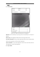
Table Of Contents
- Chapter 1 System Requirement
- Chapter 2 Network Connection
- Chapter 3 Access to the Network Camera
- Chapter 4 Live View
- Chapter 5 Network Camera Configuration
- Chapter 6 Network Settings
- Chapter 7 Video/Audio Settings
- Chapter 8 Image Settings
- Chapter 9 Event Settings
- Chapter 10 Storage Settings
- Chapter 11 Playback
- Chapter 12 Picture
- Appendix

Thermal Network Bullet Camera User Manual
93
Figure 9-16 Draw on Live View Window
4. (Optional) Check the checkbox of Enable Verification of Camera
Calibration, click the Horizontal Verify / Vertical Verify
button to draw a horizontal / vertical line on the live video, and then click the
Calculate button to calculate the line length. Compare the calculated
line length to the actual length to verify the calibration information you set.
5. If the verification results are similar, click Save to save the settings. If not, you
can click Delete to delete the drawn lines
9.3.3 Configuring Shield Region
The shield region allows you to set the specific region in which the behavior analysis
will not function. Up to 4 shield regions are supported.
Steps:
1. Enter Configuration > VCA > Shield Region.
2. Click Shield Region tab to enter the shield region configuration interface.
3. Click the hexagons sign t to draw shield area by left click end-points in
the live view window, and right click to finish the area drawing.
Notes:
Polygon area with up to 10 sides is supported.
Click to delete the drawn areas.
If live view is stopped, there is no way to draw the shield regions.
4. Click Save to save the settings.
9.3.4 Configuring Rule
The behavior analysis supports a series of behaviors, including line crossing
detection, intrusion, region entrance, and region exiting, etc.
Note: Please refer to each chapter for detailed information of each behavior.
Steps:
1. Enter Configuration > VCA > Rule.