
User Manual
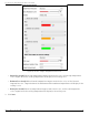
Table Of Contents
- About this Manual
- Trademarks
- Disclaimer
- Symbol Conventions
- Safety Instruction
- Laws and Regulations
- Transportation
- Power Supply
- Battery
- Maintenance
- Usage Environment
- Emergency
- Manufacturer Address
- Chapter 1 Overview
- Chapter 2 Device Activation and Accessing
- Chapter 3 Temperature Measurement
- Chapter 4 Fire Source Detection
- Fire Detection
- Smoking Detection
- 4
- 4.1 Select Recommended Scene
- 4.2 Set Fire Detection Parameters
- Before You Start
- Steps
- Fire Source Detection Mode
- 1) Go to Configuration → Event → Smart Event → Fire Source Detection Shield.
- 2) Check Enable Fire Source Detection Shield.
- 3) Click Draw Area and drag the mouse in the live view to draw the area. Release the mouse to finish drawing.
- 4) You can drag the corners of the red rectangle area to change its shape and size, or drag the rectangle to the position on demand.
- 5) Click Stop Drawing.
- 6) Click Clear All to clear all of the setting areas.
- 7) Set the value of Active Zoom Ratio on demand, and then the shield will appear only when the zoom ratio is greater than the predefined value
- 8) Click Add to save the smoke detection shield, and it will be listed in the Fire Source Detection Shield List area; you can select a region and click Delete to delete it from the list; you can also define the color of the regions.
- 9) Check Display Shield Region to show the shielded area in live view.
- Chapter 5 Behavior Analysis
- Chapter 6 Event and Alarm
- Chapter 7 Arming Schedule and Alarm Linkage
- 7
- 7.1 Set Arming Schedule
- 7.2 Linkage Method Settings
- 7
- 7.1
- 7.2
- 7.2.1 Trigger Alarm Output
- 7.2.2 FTP/NAS/Memory Card Uploading
- 7.2.3 Send Email
- Set Email
- Before You Start
- Steps
- 1) Input the sender’s e-mail information, including Sender's Address, SMTP Server, and SMTP Port.
- 2) Optional: If your e-mail server requires authentication, check Authentication and input your user name and password to log in to the server.
- 3) Set the E-mail Encryption.
- 4) Optional: If you want to receive notification with alarm pictures, check Attached Image.The notification e-mail has three attached alarm pictures about the event with configurable image capturing interval.
- 5) Input the receiver’s information, including the receiver’s name and address.
- 6) Click Test to see if the function is properly configured.
- 7.2.4 Notify Surveillance Center
- 7.2.5 Trigger Recording
- 7.2.6 Set Audible Alarm Output
- 7.2.7 Set Flashing Alarm Light Output
- Chapter 8 Live View
- Chapter 9 Video and Audio
- 9
- 9.1 Video Settings
- 9.2 Display Settings
- 9
- 9.1
- 9.2
- 9.3 OSD
- 9.4 Set Privacy Mask
- 9.5 Overlay Picture
- 9.6 Set Manual DPC (Defective Pixel Correction)
- Chapter 10 Video Recording and Picture Capture
- Chapter 11 Network Settings
- Chapter 12 System and Security
- 12
- 12.1 View Device Information
- 12.2 Search and Manage Log
- 12.3 Import and Export Configuration File
- Steps
- 1) Go to Configuration → System → Maintenance → Upgrade & Maintenance.
- 2) Click Device Parameters and input the encryption password to export the current configuration file.
- 3) Set the saving path to save the configuration file in a local computer.
- 1) Access the device that needs to be configured via a Web browser.
- 2) Click Browse to select the saved configuration file.
- 3) Input the encryption password you set when exporting the configuration file.
- 4) Click Import.
- Steps
- 12.4 Export Diagnose Information
- 12.5 Reboot
- 12.6 Restore and Default
- 12.7 Upgrade
- 12.8 View Open Source Software License
- 12.9 Time and Date
- 12.10 Set RS-232
- 12.11 Set RS-485
- 12.12 Set Same Unit
- 12.13 Security
- 12.14 User and Account
- Chapter 13 Appendix

DS-2TD2137-7P Thermal Network Camera User Manual
UM DS-2TD2137-7P 042021NA 46
Scene Mode
There are several sets of image parameters predefined for different installation environments. Select a
scene according to the actual installation environment to speed up the display settings.
OSD
You can customize OSD (On-screen Display) information such as device name, time/date, font, color, and
text overlay displayed on video stream.
Go to OSD setting page: Configuration → Image → OSD Settings. Set the corresponding parameters, and click
Save to take effect.
• Displayed Information: Set camera name, date, week, and their related display format.
• Text Overlay: Set customized overlay text on image.
• OSD Parameters: Set OSD parameters, such as Display Mode, OSD Size, and Font Color.
Set Privacy Mask
The function blocks certain areas in the live view to protect privacy. No matter how the device moves, the
blocked areas will never be seen.
Steps
1. Go to privacy mask setting page: Configuration → Image → Privacy Mask.
2. Check Enable Privacy Mask.
3. Click Draw Area. Drag the mouse in the live view to draw a closed area.
• Drag the corners of the area: Adjust the size of the area.
• Drag the area: Adjust the position of the area.
• Click Clear All: Clear all the areas you set.
4. Click Stop Drawing.
5. Click Save.
NOTE: Up to four areas are supported for setting.
Overlay Picture
Overlay a customized picture on live view.
Before You Start
The picture to overlay has to be in 24-bit BMP format, and the maximum picture size is 128 × 128 pixels.