
User Manual
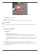
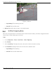
Table Of Contents
- About this Manual
- Trademarks
- Disclaimer
- Symbol Conventions
- Safety Instruction
- Laws and Regulations
- Transportation
- Power Supply
- Battery
- Maintenance
- Usage Environment
- Emergency
- Manufacturer Address
- Chapter 1 Overview
- Chapter 2 Device Activation and Accessing
- Chapter 3 Temperature Measurement
- Chapter 4 Fire Source Detection
- Fire Detection
- Smoking Detection
- 4
- 4.1 Select Recommended Scene
- 4.2 Set Fire Detection Parameters
- Before You Start
- Steps
- Fire Source Detection Mode
- 1) Go to Configuration → Event → Smart Event → Fire Source Detection Shield.
- 2) Check Enable Fire Source Detection Shield.
- 3) Click Draw Area and drag the mouse in the live view to draw the area. Release the mouse to finish drawing.
- 4) You can drag the corners of the red rectangle area to change its shape and size, or drag the rectangle to the position on demand.
- 5) Click Stop Drawing.
- 6) Click Clear All to clear all of the setting areas.
- 7) Set the value of Active Zoom Ratio on demand, and then the shield will appear only when the zoom ratio is greater than the predefined value
- 8) Click Add to save the smoke detection shield, and it will be listed in the Fire Source Detection Shield List area; you can select a region and click Delete to delete it from the list; you can also define the color of the regions.
- 9) Check Display Shield Region to show the shielded area in live view.
- Chapter 5 Behavior Analysis
- Chapter 6 Event and Alarm
- Chapter 7 Arming Schedule and Alarm Linkage
- 7
- 7.1 Set Arming Schedule
- 7.2 Linkage Method Settings
- 7
- 7.1
- 7.2
- 7.2.1 Trigger Alarm Output
- 7.2.2 FTP/NAS/Memory Card Uploading
- 7.2.3 Send Email
- Set Email
- Before You Start
- Steps
- 1) Input the sender’s e-mail information, including Sender's Address, SMTP Server, and SMTP Port.
- 2) Optional: If your e-mail server requires authentication, check Authentication and input your user name and password to log in to the server.
- 3) Set the E-mail Encryption.
- 4) Optional: If you want to receive notification with alarm pictures, check Attached Image.The notification e-mail has three attached alarm pictures about the event with configurable image capturing interval.
- 5) Input the receiver’s information, including the receiver’s name and address.
- 6) Click Test to see if the function is properly configured.
- 7.2.4 Notify Surveillance Center
- 7.2.5 Trigger Recording
- 7.2.6 Set Audible Alarm Output
- 7.2.7 Set Flashing Alarm Light Output
- Chapter 8 Live View
- Chapter 9 Video and Audio
- 9
- 9.1 Video Settings
- 9.2 Display Settings
- 9
- 9.1
- 9.2
- 9.3 OSD
- 9.4 Set Privacy Mask
- 9.5 Overlay Picture
- 9.6 Set Manual DPC (Defective Pixel Correction)
- Chapter 10 Video Recording and Picture Capture
- Chapter 11 Network Settings
- Chapter 12 System and Security
- 12
- 12.1 View Device Information
- 12.2 Search and Manage Log
- 12.3 Import and Export Configuration File
- Steps
- 1) Go to Configuration → System → Maintenance → Upgrade & Maintenance.
- 2) Click Device Parameters and input the encryption password to export the current configuration file.
- 3) Set the saving path to save the configuration file in a local computer.
- 1) Access the device that needs to be configured via a Web browser.
- 2) Click Browse to select the saved configuration file.
- 3) Input the encryption password you set when exporting the configuration file.
- 4) Click Import.
- Steps
- 12.4 Export Diagnose Information
- 12.5 Reboot
- 12.6 Restore and Default
- 12.7 Upgrade
- 12.8 View Open Source Software License
- 12.9 Time and Date
- 12.10 Set RS-232
- 12.11 Set RS-485
- 12.12 Set Same Unit
- 12.13 Security
- 12.14 User and Account
- Chapter 13 Appendix

DS-2TD2137-7P Thermal Network Camera User Manual
UM DS-2TD2137-7P 042021NA 24
• When the rule type is selected as Intrusion, Region Entrance, Region Entrance, click to draw an
area in live view. Right click the mouse to finish drawing.
• Duration: The device performs behavior analysis when the target stays in the detection area for
more than the setting value.
NOTE: Draw three segments of the rule from near to far to cover all of the detection area.
6. Check to enable Filter by Pixel, then Draw max size and min size rectangles to filter the target among
human, vehicle, animal, and others. Only targets whose size is between the Max. Size and Min. Size
valuse will trigger the alarm.
NOTE: You can draw the max size and min size rectangles according to the real target in the
scene. The recommended size is 1.2 times the target.
Due to the main difference between humans and animals is the height, just be
concerned with the height of the animal.
Click to copy the same settings to other rules.
7. Click Save.
8. Optional: You can shield certain areas from being detected. Refer to Set Shielded Region for detailed
settings.
NOTE: Repeat steps above to configure multiply rules. Set the arming schedule and linkage
method for each rule.
9. Refer to Set Arming Schedule for setting scheduled time. Refer to Linkage Method Settings for setting
linkage method.
Advanced Configuration
Go to Configuration → VCA → Advanced Configuration and configure the parameters.
Detection Parameters
• Detection Sensitivity: The higher the sensitivity, the easier the target will be detected.
• Background Update Rate: If a detected target remains in the monitoring scene for a certain time, the
system will count the target as the background automatically. The greater the value, the faster the
target will be counted as the background.
• Minimum Target Size: The system will filter out the object smaller than the minimum target size.
• Displacement Constraint for Target Generation: The higher the value, the slower the target is
generated, and the higher the analysis accuracy.
• Optical-Axis Movement: Check function when target moves in the direction of camera’s optical-axis.
• When the target is far from the device and the movement is not clear, enable this function to check
the move direction.