
User Manual
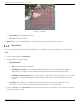
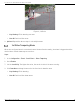
Table Of Contents
- About this Manual
- Trademarks
- Disclaimer
- Symbol Conventions
- Safety Instruction
- Laws and Regulations
- Transportation
- Power Supply
- Battery
- Maintenance
- Usage Environment
- Emergency
- Manufacturer Address
- Chapter 1 Overview
- Chapter 2 Device Activation and Accessing
- Chapter 3 Temperature Measurement
- Chapter 4 Fire Source Detection
- Fire Detection
- Smoking Detection
- 4
- 4.1 Select Recommended Scene
- 4.2 Set Fire Detection Parameters
- Before You Start
- Steps
- Fire Source Detection Mode
- 1) Go to Configuration → Event → Smart Event → Fire Source Detection Shield.
- 2) Check Enable Fire Source Detection Shield.
- 3) Click Draw Area and drag the mouse in the live view to draw the area. Release the mouse to finish drawing.
- 4) You can drag the corners of the red rectangle area to change its shape and size, or drag the rectangle to the position on demand.
- 5) Click Stop Drawing.
- 6) Click Clear All to clear all of the setting areas.
- 7) Set the value of Active Zoom Ratio on demand, and then the shield will appear only when the zoom ratio is greater than the predefined value
- 8) Click Add to save the smoke detection shield, and it will be listed in the Fire Source Detection Shield List area; you can select a region and click Delete to delete it from the list; you can also define the color of the regions.
- 9) Check Display Shield Region to show the shielded area in live view.
- Chapter 5 Behavior Analysis
- Chapter 6 Event and Alarm
- Chapter 7 Arming Schedule and Alarm Linkage
- 7
- 7.1 Set Arming Schedule
- 7.2 Linkage Method Settings
- 7
- 7.1
- 7.2
- 7.2.1 Trigger Alarm Output
- 7.2.2 FTP/NAS/Memory Card Uploading
- 7.2.3 Send Email
- Set Email
- Before You Start
- Steps
- 1) Input the sender’s e-mail information, including Sender's Address, SMTP Server, and SMTP Port.
- 2) Optional: If your e-mail server requires authentication, check Authentication and input your user name and password to log in to the server.
- 3) Set the E-mail Encryption.
- 4) Optional: If you want to receive notification with alarm pictures, check Attached Image.The notification e-mail has three attached alarm pictures about the event with configurable image capturing interval.
- 5) Input the receiver’s information, including the receiver’s name and address.
- 6) Click Test to see if the function is properly configured.
- 7.2.4 Notify Surveillance Center
- 7.2.5 Trigger Recording
- 7.2.6 Set Audible Alarm Output
- 7.2.7 Set Flashing Alarm Light Output
- Chapter 8 Live View
- Chapter 9 Video and Audio
- 9
- 9.1 Video Settings
- 9.2 Display Settings
- 9
- 9.1
- 9.2
- 9.3 OSD
- 9.4 Set Privacy Mask
- 9.5 Overlay Picture
- 9.6 Set Manual DPC (Defective Pixel Correction)
- Chapter 10 Video Recording and Picture Capture
- Chapter 11 Network Settings
- Chapter 12 System and Security
- 12
- 12.1 View Device Information
- 12.2 Search and Manage Log
- 12.3 Import and Export Configuration File
- Steps
- 1) Go to Configuration → System → Maintenance → Upgrade & Maintenance.
- 2) Click Device Parameters and input the encryption password to export the current configuration file.
- 3) Set the saving path to save the configuration file in a local computer.
- 1) Access the device that needs to be configured via a Web browser.
- 2) Click Browse to select the saved configuration file.
- 3) Input the encryption password you set when exporting the configuration file.
- 4) Click Import.
- Steps
- 12.4 Export Diagnose Information
- 12.5 Reboot
- 12.6 Restore and Default
- 12.7 Upgrade
- 12.8 View Open Source Software License
- 12.9 Time and Date
- 12.10 Set RS-232
- 12.11 Set RS-485
- 12.12 Set Same Unit
- 12.13 Security
- 12.14 User and Account
- Chapter 13 Appendix

DS-2TD2137-7P Thermal Network Camera User Manual
UM DS-2TD2137-7P 042021NA 22
NOTE: After auto calibration, refer to Verify the Calibration Result to verify if the calibration
is successful. Set manual calibration if the auto calibration failed or the verified
result are bad.
Result
After calibration, the height and angle of camera will be shown in live view.
Calibrate Manually
Steps
1. Go to Configuration → VCA → Camera Calibration.
2. Check Manual Calibration.
3. Click Fig 1. Click and drag the vertical line until it fits the target.
4. Enter the actual length of the calibration line.
5. Repeat steps above to set Fig 2, Fig 3, and Fig 4.
NOTE: Draw a calibration line in each figure, and the four calibration lines should be evenly
distributed in the same horizontal plane from left to right.
In the four figures, the calibrated object doesn’t need to be the same. Select a
proper object in each figure.
6. Optional: Click to delete the calibration line.
7. Click Save.
CAUTION: Separate four vertical lines in the optical-axis direction at the close site, middle, and
far site respectively.
Separate four vertical lines at the left, middle, and right of the image respectively.
If manual calibration’s result is incorrect, select another target to recalibrate.
After manual calibration, refer to Verify the Calibration Result to verify that the
calibration is successful.
Result
After calibration, the height and angle of camera will be shown in live view.
Verify the Calibration Result
The function can verify whether the calibrated value is consistent with the actual value.
Steps
1. Click .
2. Click , and drag a vertical line in the view.