
Quick Start Guide
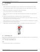
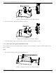
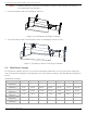
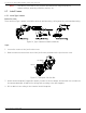
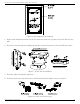
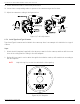
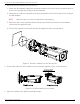
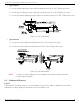
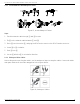
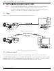
Table Of Contents
- Regulatory Information
- EU Conformity Statement
- Laws and Regulations
- Storage
- Transportation
- Installation
- Power Supply
- Battery
- System Security
- Maintenance
- Usage Environment
- Emergency
- 1. Appearance Description
- 2. Installation
- 3. Set the Network Camera over the LAN
- 4. Access via Web Browser
- 5. Appendix

DS-2TD2137-7P Thermal Network Bullet Camera Quick Start Guide
QSG DS-2TD2137-7P 041521NA 16
9.
Fix the delivered screws to secure the junction box.
10.
Connect the corresponding cables to power on the camera and get the live view.
11.
Adjust the camera according to the figure below.
Figure 19, 3-Axis Adjustment
2.3.2 Install Type II and Type III Camera
Type II and Type III cameras are installed in the same way. Here is an example of installation for a type II
camera.
Steps
1.
Attach the drill template (supplied) to the where you want to fix the camera, and then drill the screw
holes in the ceiling/wall according to the drill template.
2.
(Optional) If you want to route cables through the installation surface, drill a cable hole according to
the drill template.
NOTE: Skip this step if you route the cable via the side opening.
Figure 20, Drill Template