
Quick Start Guide
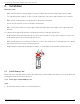
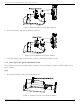
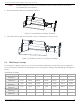
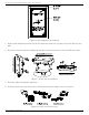
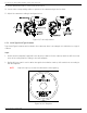
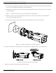
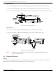
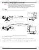
Table Of Contents
- Regulatory Information
- EU Conformity Statement
- Laws and Regulations
- Storage
- Transportation
- Installation
- Power Supply
- Battery
- System Security
- Maintenance
- Usage Environment
- Emergency
- 1. Appearance Description
- 2. Installation
- 3. Set the Network Camera over the LAN
- 4. Access via Web Browser
- 5. Appendix

DS-2TD2137-7P Thermal Network Bullet Camera Quick Start Guide
QSG DS-2TD2137-7P 041521NA 15
Figure 16, Drill Template (Type I Camera)
5.
Align the drill template hole with the junction box base screw hole to place the junction box onto the
wall.
6.
Route the screw through the sealing ring, and fix the junction box base on the wall with the screws.
Figure 17, Install Junction Box Base
7.
Route the cables through the cable hole.
8.
Insert the latches into the latch holes to affix the bracket and camera to the junction box.
Figure 18, Install Junction Box Cover