
Quick Start Guide
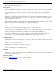
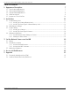
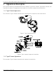
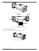
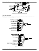
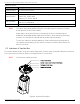
Table Of Contents
- Regulatory Information
- EU Conformity Statement
- Laws and Regulations
- Storage
- Transportation
- Installation
- Power Supply
- Battery
- System Security
- Maintenance
- Usage Environment
- Emergency
- 1. Appearance Description
- 2. Installation
- 3. Set the Network Camera over the LAN
- 4. Access via Web Browser
- 5. Appendix

DS-2TD2137-7P Thermal Network Bullet Camera Quick Start Guide
QSG DS-2TD2137-7P 041521NA 10
Cable Description
Name
Description
Power Interface
For 12 VDC or 24 VAC power supply, make sure that the positive/negative terminals
are connected correctly
Network Interface
Connect to the LAN interface, PoE (802.3af) is supported
Alarm Interface
Two-way alarm input and alarm output are supported
Alarm In: IN1, G/IN2, and G
Alarm Out: 1A, 1B/2A, and 2B
Audio Interface
Audio In: Pickup
Audio Out: Loudspeaker
RS-485 Interface
Control line
NOTE: The cables may vary by model. Here we list all cable types for reference. See the
actual product for the correct cables.
Alarm cables can be classified as 2-ch alarm inputs and 2-ch alarm outputs.
ALARM-IN1 and ALARM-IN2 are alarm input interfaces, and G indicates grounding
interface. (1A, 1B) and (2A, 2B) indicate two alarm output interfaces.
To reset the camera to default parameters, hold the Reset button and power on
the camera. After powering on the camera, continue to hold the Reset button for
about 10 seconds.
1.5
Interfaces of Junction Box
For certain camera models, the power cable, alarm cable, network cable, and audio cable are connected
to the junction box interfaces. Refer to the figure below for connections.
NOTE: Junction boxes differ by model.
Figure 8, Interface Description