DS-2TD2137-7P Thermal Network Bullet Camera Quick Start Guide
DS-2TD2137-7P Thermal Network Bullet Camera Quick Start Guide © 2021 Hangzhou Hikvision Digital Technology Co., Ltd. All rights reserved. About this Manual The Manual includes instructions for using and managing the Product. Pictures, charts, images and all other information hereinafter are for description and explanation only. The information contained in the Manual is subject to change, without notice, due to firmware updates or other reasons.
DS-2TD2137-7P Thermal Network Bullet Camera Quick Start Guide FCC Compliance: This equipment has been tested and found to comply with the limits for Class A device, pursuant to part 15 of the FCC Rules. These limits are designed to provide reasonable protection against harmful interference when the equipment is operated in a commercial environment.
DS-2TD2137-7P Thermal Network Bullet Camera Quick Start Guide Laws and Regulations • The lightning protection and grounding design of outdoor installation and wiring should be in compliance with the lightning protection requirements of the buildings and local laws and regulations. • Use of the product must be in strict compliance with the local electrical safety regulations. Storage • Store the device in dry, well-ventilated, corrosive-gas-free, no direct sunlight, and no heating source environment.
DS-2TD2137-7P Thermal Network Bullet Camera Quick Start Guide • For long-term storage of the battery, make sure it is fully charged every half year to ensure the battery quality. Otherwise, damage may occur.
DS-2TD2137-7P Thermal Network Bullet Camera Quick Start Guide Table of Contents 1. Appearance Description 1.1 1.2 1.3 1.4 1.5 Type I Camera Appearance Type II Camera Appearance Type III Camera Appearance Cable Description Interfaces of Junction Box 2. Installation 2.1 2.2 2.3 2.4 3.3 11 20 Wiring 20 Activate the Camera 20 3.2.1 Activate via Web Browser ......................................................................................................... 21 3.2.2 Activate via SADP Software ......
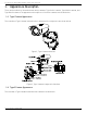
DS-2TD2137-7P Thermal Network Bullet Camera Quick Start Guide 1. Appearance Description There are three kinds of thermal network bullet cameras: Type I bullet camera, Type II bullet camera, and Type III bullet camera. The appearance descriptions of the three cameras are shown below. 1.1 Type I Camera Appearance The overview of Type I thermal network bullet camera and its components are shown below. Figure 1, Type I Camera Overview Figure 2, Type I Camera Components Overview 1.
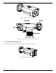
DS-2TD2137-7P Thermal Network Bullet Camera Quick Start Guide Figure 3, Type II Camera Overview Figure 4, Type II Camera Components Overview 1.3 Type III Camera Appearance The overview of Type III thermal network bullet camera is shown below.
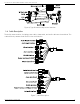
DS-2TD2137-7P Thermal Network Bullet Camera Quick Start Guide Figure 6, Type III Camera Components Overview 1.4 Cable Description The bullet camera cables, including power cable, alarm cable, and audio cable are shown below. The cables differ by camera model. Refer to the actual device.
DS-2TD2137-7P Thermal Network Bullet Camera Quick Start Guide Cable Description Name Description For 12 VDC or 24 VAC power supply, make sure that the positive/negative terminals Power Interface are connected correctly Network Interface Connect to the LAN interface, PoE (802.
DS-2TD2137-7P Thermal Network Bullet Camera Quick Start Guide 2. Installation Before You Start • Make sure the device in the package is in good condition and all the assembly parts are included. • The standard power supply is 12 VDC or 24 VAC. Make sure your power supply matches your camera. • Make sure all related devices are powered off during the installation. • Check the specification for the installation environment.
DS-2TD2137-7P Thermal Network Bullet Camera Quick Start Guide Figure 9, Remove Card Slot Cover (Type I Camera) 2. Insert the memory card into the memory card slot. Figure 10, Insert Memory Card (Type I Camera) 3. Cover the memory card slot and fix the screws on the memory card slot cover. 2.1.2 Install Type II and Type III Camera Memory Card The installation for the two cameras types is same. Here is an example of memory card installation for a type II camera. Steps 1.
DS-2TD2137-7P Thermal Network Bullet Camera Quick Start Guide NOTE: A rubber seal ring is on the top of the memory card slot cover. Do NOT lose the ring for the waterproof performance. 2. Insert the memory card into the memory card slot. Figure 12, Insert Memory Card (Type II Camera) 3. Cover the memory card slot and fix the screws on the memory card slot cover. Figure 13, Fix Memory Card Slot Cover (Type II Camera) 2.
DS-2TD2137-7P Thermal Network Bullet Camera Quick Start Guide NOTE: 2.3 This table is for reference only, and the actual detection range may vary by camera settings, mounting condition, monitor, etc. Install Camera 2.3.1 Install Type I Camera Before You Start There are three Type I camera installation methods: wall mounting, ceiling mounting, and stand mounting. Figure 14, Type I Camera Installation Methods Steps 1. Loosen the screws on the junction box cover. 2.
DS-2TD2137-7P Thermal Network Bullet Camera Quick Start Guide Figure 16, Drill Template (Type I Camera) 5. Align the drill template hole with the junction box base screw hole to place the junction box onto the wall. 6. Route the screw through the sealing ring, and fix the junction box base on the wall with the screws. Figure 17, Install Junction Box Base 7. Route the cables through the cable hole. 8. Insert the latches into the latch holes to affix the bracket and camera to the junction box.
DS-2TD2137-7P Thermal Network Bullet Camera Quick Start Guide 9. Fix the delivered screws to secure the junction box. 10. Connect the corresponding cables to power on the camera and get the live view. 11. Adjust the camera according to the figure below. Figure 19, 3-Axis Adjustment 2.3.2 Install Type II and Type III Camera Type II and Type III cameras are installed in the same way. Here is an example of installation for a type II camera. Steps 1.
DS-2TD2137-7P Thermal Network Bullet Camera Quick Start Guide 3. (Optional) Affix the camera to the junction box. 1) Attach the drill template (supplied) to the where you want to fix the junction box, and then drill four holes in the ceiling/wall according to the drill template. 2) (Optional) If you want to route cables through the installation surface, drill a cable hole according to the drill template.
DS-2TD2137-7P Thermal Network Bullet Camera Quick Start Guide ● Type I Bracket 1) Loosen the pan adjusting screw to adjust panning position [0° to 360°]. Tighten the screw. 2) Loosen the tile adjusting screw to adjust the tilting position [0° to 100°]. Tighten the screw. 3) Loosen the rotation adjusting screw to adjust the rotation position [0° to 360°]. Tighten the screw. Figure 23, 3-Axis Adjustment ● Type II Bracket 1) Loosen the screw to adjust the tilting position [0° to 90°]. Tighten the screw.
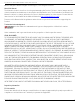
DS-2TD2137-7P Thermal Network Bullet Camera Quick Start Guide 2.4.1 Install Network Cable Waterproof Jacket Figure 25, Install Waterproof Jacket Steps 1. Feed the network cable through ① and ③ in order. 2. Fix ② on the network cable between ① and ③. 3. Place ⑤ onto the end of ⑥, and plug the RJ-45 male connector into RJ-45 female connector. 4. Screw ③ to ⑥ clockwise. 5. Push ② into ③. 6. Secure ① with the ③ in a clockwise direction. 2.4.
DS-2TD2137-7P Thermal Network Bullet Camera Quick Start Guide 3. Set the Network Camera over the LAN NOTE: 3.1 You shall acknowledge that the use of the product with Internet access might be under network security risks. For avoidance of any network attacks and information leakage, strengthen your own protection. If the product does not work properly, contact with your dealer or the nearest service center. Wiring Connect the camera to the network according to the following figures.
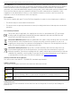
DS-2TD2137-7P Thermal Network Bullet Camera Quick Start Guide 3.2.1 Activate via Web Browser Steps 1. Power on the camera, and connect the camera to the network. 2. Input the IP address into the address bar of the Web browser, and click Enter to enter the activation interface. NOTE: The default IP address of the camera is 192.168.1.64. For cameras that enable DHCP by default, activate the camera via SADP software and search for the IP address. Figure 29, Activation Interface (Web) 3.
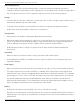
DS-2TD2137-7P Thermal Network Bullet Camera Quick Start Guide Steps 1. Run the SADP software to search for online devices. 2. Check the device status from the device list, and select the inactive device. Figure 30, SADP Interface The SADP software supports activating the camera in batch. See the SADP software user manual for details. 3. Input the password in the password field, and confirm the password.
DS-2TD2137-7P Thermal Network Bullet Camera Quick Start Guide Steps 1. Run the SADP software. 2. Select an active device. NOTE: Refer to Chapter 3.2 to activate the camera if the camera is inactive. 3. Change the device IP address to the same subnet as your computer by either modifying the IP address manually or checking the Enable DHCP checkbox. Figure 31, Modify the IP Address 4. Input the password to activate your IP address modification. NOTE: 4. Batch IP address modification is supported by SADP.
DS-2TD2137-7P Thermal Network Bullet Camera Quick Start Guide • Web Browser: Internet Explorer 8.0 and above version, Apple Safari 5.0.2 and above version, Mozilla Firefox 5.0 and above version, or Google Chrome 18 and above version Steps 1. Open the Web browser. 2. In the browser address bar, input the IP address of the network camera, and press the Enter key to enter the login interface. NOTE: The default IP address is 192.168.1.64.
DS-2TD2137-7P Thermal Network Bullet Camera Quick Start Guide 5. Appendix 5.1 Frequently Asked Questions (FAQ) Device Running Error Question: The device fails to start or reboots repeatedly. Answer: Examine the power supply of the device and see whether it meets the requirements. Select the power supply as close as possible. Examine the power cord and see whether it meets the requirements. Device Upgrading Question: Device fails to upgrade.