
User Manual


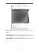
Table Of Contents
- Chapter 1 System Requirement
- Chapter 2 Network Connection
- Chapter 3 Access to the Network Camera
- Chapter 4 Live View
- Chapter 5 Network Camera Configuration
- Chapter 6 Network Settings
- Chapter 7 Video/Audio Settings
- Chapter 8 Image Settings
- Chapter 9 Event Settings
- Chapter 10 Storage Settings
- Chapter 11 Playback
- Chapter 12 Picture
- Appendix

Thermal Network Bullet Camera User Manual
92
Figure 9-16 Draw on Live View Window
Note:
Set 4 to 8 valid calibration lines for the camera. See figure below, 4 vertical
lines are recommended. Make sure you separate the vertical lines at the left,
middle and right of the image respectively. You can calibrate it with 4 persons
standing in the view (knowing their heights), or with only one person standing
in four different positions within the view.
5. You can click to delete the drawn lines.
6. Click Save to save the settings.
9.3.3 Configuring Shield Region
The shield region allows you to set the specific region in which the behavior analysis
will not function. Up to 4 shield regions are supported.
Steps:
1. Enter Configuration > VCA > Shield Region.
2. Click Shield Region tab to enter the shield region configuration interface.