
User Manual


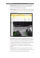

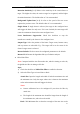


Table Of Contents
- Chapter 1 System Requirement
- Chapter 2 Network Connection
- Chapter 3 Access to the Network Camera
- Chapter 4 Live View
- Chapter 5 Network Camera Configuration
- 5.1 Configuring Local Parameters
- 5.2 Configuring Time Settings
- 5.3 Configuring Network Settings
- 5.3.1 Configuring TCP/IP Settings
- 5.3.2 Configuring Port Settings
- 5.3.3 Configuring PPPoE Settings
- 5.3.4 Configuring DDNS Settings
- 5.3.5 Configuring SNMP Settings
- 5.3.6 Configuring 802.1X Settings
- 5.3.7 Configuring QoS Settings
- 5.3.8 Configuring UPnP™ Settings
- 5.3.9 Email Sending Triggered by Alarm
- 5.3.10 Configuring NAT (Network Address Translation) Settings
- 5.3.11 Configuring FTP Settings
- 5.3.12 HTTPS Settings
- 5.4 Configuring Video and Audio Settings
- 5.5 Configuring Image Parameters
- 5.6 Configuring and Handling Alarm Events
- 5.7 Temperature Measurement
- 5.8 VCA Configuration
- Chapter 6 Storage Settings
- Chapter 7 Playback
- Chapter 8 Log Searching
- Chapter 9 Others
- Appendix

Thermometric Network Bullet Camera User Manual
82
1:35m
2:45m
3:6m
4:4m
Figure 5-51 Draw on Live View Window
3. Draw the Shield Region
The shield region allows you to set the specific region in which the behavior analysis
will not function. Up to 4 shield regions are supported.
Steps:
1) Enter the Shield Region setting interface:
Configuration > VCA Configuration > Shield Region
2) Click Draw Area. Draw area by left click end-points in the live view window,
and right click to finish the area drawing.
Notes:
● Polygon area with up to 10 sides is supported.
● Click Delete to delete the drawn areas.
● If live view is stopped, there is no way to draw the shield regions.
3) Click Save to save the settings.
4. Configure the Rule