
User Manual

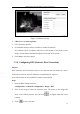


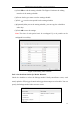

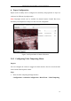


Table Of Contents
- Chapter 1 System Requirement
- Chapter 2 Network Connection
- Chapter 3 Access to the Network Camera
- Chapter 4 Live View
- Chapter 5 Network Camera Configuration
- 5.1 Configuring Local Parameters
- 5.2 Configuring Time Settings
- 5.3 Configuring Network Settings
- 5.3.1 Configuring TCP/IP Settings
- 5.3.2 Configuring Port Settings
- 5.3.3 Configuring PPPoE Settings
- 5.3.4 Configuring DDNS Settings
- 5.3.5 Configuring SNMP Settings
- 5.3.6 Configuring 802.1X Settings
- 5.3.7 Configuring QoS Settings
- 5.3.8 Configuring UPnP™ Settings
- 5.3.9 Email Sending Triggered by Alarm
- 5.3.10 Configuring NAT (Network Address Translation) Settings
- 5.3.11 Configuring FTP Settings
- 5.3.12 HTTPS Settings
- 5.4 Configuring Video and Audio Settings
- 5.5 Configuring Image Parameters
- 5.6 Configuring and Handling Alarm Events
- 5.7 Temperature Measurement
- 5.8 VCA Configuration
- Chapter 6 Storage Settings
- Chapter 7 Playback
- Chapter 8 Log Searching
- Chapter 9 Others
- Appendix

Thermometric Network Bullet Camera User Manual
70
1. Enter the Alarm Input Settings interface:
Configuration > Advanced Configuration> Basic Event > Alarm Input
2. Choose the alarm input No. and the Alarm Type. The alarm type can be NO
(Normally Open) and NC (Normally Closed). Edit the name to set a name for the
alarm input (optional).
Figure 5-42 Alarm Input Settings
3. Click Edit to set the arming schedule for the alarm input. Refer to Task 2 Set the
Arming Schedule for Motion Detection in Section 5.6.1.
4. Check the checkbox to select the linkage method taken for the alarm input. Refer
to Task 3 Set the Alarm Actions for Motion Detection in Section 5.6.1.
5. You can also choose the PTZ linking for the alarm input if your camera is
installed with a pan/tilt unit. Check the relative checkbox and select the No. to
enable Preset Calling, Patrol Calling or Pattern Calling.
6. You can copy your settings to other alarm inputs.
7. Click Save to save the settings.