
User Manual


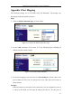
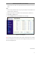
Table Of Contents
- Chapter 1 System Requirement
- Chapter 2 Network Connection
- Chapter 3 Access to the Network Camera
- Chapter 4 Live View
- Chapter 5 Network Camera Configuration
- 5.1 Configuring Local Parameters
- 5.2 Configuring Time Settings
- 5.3 Configuring Network Settings
- 5.3.1 Configuring TCP/IP Settings
- 5.3.2 Configuring Port Settings
- 5.3.3 Configuring PPPoE Settings
- 5.3.4 Configuring DDNS Settings
- 5.3.5 Configuring SNMP Settings
- 5.3.6 Configuring 802.1X Settings
- 5.3.7 Configuring QoS Settings
- 5.3.8 Configuring UPnP™ Settings
- 5.3.9 Email Sending Triggered by Alarm
- 5.3.10 Configuring NAT (Network Address Translation) Settings
- 5.3.11 Configuring FTP Settings
- 5.3.12 HTTPS Settings
- 5.4 Configuring Video and Audio Settings
- 5.5 Configuring Image Parameters
- 5.6 Configuring and Handling Alarm Events
- 5.7 Temperature Measurement
- 5.8 VCA Configuration
- Chapter 6 Storage Settings
- Chapter 7 Playback
- Chapter 8 Log Searching
- Chapter 9 Others
- Appendix

Thermometric Network Bullet Camera User Manual
116
Appendix 2 Port Mapping
The following settings are for TP-LINK router (TL-WR641G). The settings vary
depending on different models of routers.
Steps:
1. Select the WAN Connection Type, as shown below:
Figure A.2.1 Select the WAN Connection Type
2. Set the LAN parameters of the router as in the following figure, including IP
address and subnet mask settings.
Figure A.2.2 Set the LAN parameters
3. Set the port mapping in the virtual severs of Forwarding. By default, camera uses
port 80, 8000 and 554. You can change these ports value with web browser or
client software.
Example:
When the cameras are connected to the same router, you can configure the ports of
a camera as 80, 8000, and 554 with IP address 192.168.1.23, and the ports of