
User Manual
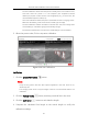
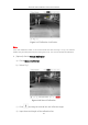
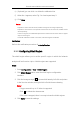
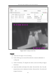
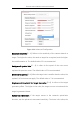
Table Of Contents
- Chapter 1 Overview
- Chapter 2 Network Connection
- Chapter 3 Access to the Network Camera
- Chapter 4 Live View
- Chapter 5 Network Camera Configuration
- Chapter 6 Network Settings
- Chapter 7 Video/Audio Settings
- Chapter 8 Image Settings
- Chapter 9 Event Settings
- Chapter 10 Storage Settings
- Chapter 11 Open Platform setting
- Chapter 12 Playback
- Chapter 13 Picture
- Appendix

Thermal Network Bullet Camera User Manual
123
e) (Optional) you can click × to delete the calibration line.
f) When the √ appears, select Fig 2 to 4 and repeat step 3.
g) Click Save.
Notes:
Separate 4 vertical lines at the left, middle and right of the image respectively.
Separate 4 vertical lines in the optical-axis direction at the close site, middle and far
site respectively.
In the four figures, the calibrated object doesn't need to be the same. Select a proper
object in each figure.
If manual calibration’s result is incorrect, reset the target to recalibrate.
Verification:
Refer to the verification procedure of Auto Calibration.
9.3.3 Configuring Shield Region
The shield region allows you to set the specific region in which the behavior
analysis will not function. Up to 4 shield regions are supported.
Steps:
1. Enter Configuration > VCA > Shield Region.
2. Click Shield Region tab to enter the shield region configuration
interface.
3. Click the hexagons sign to draw shield area by left click end-points
in the live view window, and right click to finish the area drawing.
Notes:
Polygon area with up to 10 sides is supported.
Click to delete the drawn areas.
If live view is stopped, there is no way to draw the shield regions.
4. Click Save to save the settings.