Thermal Network Bullet Camera Quick Start Guide COPYRIGHT © 2019 Hangzhou Hikvision Digital Technology Co., Ltd.
Quick Start Guide COPYRIGHT © 2019 Hangzhou Hikvision Digital Technology Co., Ltd. ALL RIGHTS RESERVED. Any and all information, including, among others, wordings, pictures, graphs are the properties of Hangzhou Hikvision Digital Technology Co., Ltd. or its subsidiaries (hereinafter referred to be “Hikvision”).
TO THE MAXIMUM EXTENT PERMITTED BY APPLICABLE LAW, THE PRODUCT DESCRIBED, WITH ITS HARDWARE, SOFTWARE AND FIRMWARE, IS PROVIDED “AS IS”, WITH ALL FAULTS AND ERRORS, AND HIKVISION MAKES NO WARRANTIES, EXPRESS OR IMPLIED, INCLUDING WITHOUT LIMITATION, MERCHANTABILITY, SATISFACTORY QUALITY, FITNESS FOR A PARTICULAR PURPOSE, AND NON-INFRINGEMENT OF THIRD PARTY.
FCC Information FCC compliance: This equipment has been tested and found to comply with the limits for Class A device, pursuant to part 15 of the FCC Rules. These limits are designed to provide reasonable protection against harmful interference when the equipment is operated in a commercial environment. This equipment generates, uses, and can radiate radio frequency energy and, if not installed and used in accordance with the instruction manual, may cause harmful interference to radio communications.
upon the purchase of equivalent new equipment, or dispose of it at designated collection points. For more information see: www.recyclethis.info 2006/66/EC (battery directive): This product contains a battery that cannot be disposed of as unsorted municipal waste in the European Union. See the product documentation for specific battery information. The battery is marked with this symbol, which may include lettering to indicate cadmium (Cd), lead (Pb), or mercury (Hg).
Warnings Follow these safeguards to prevent serious injury or death. Cautions Follow these precautions to prevent potential injury or material damage. Warnings ● Proper configuration of all passwords and other security settings is the responsibility of the installer and/or end-user. ● In the use of the product, you must be in strict compliance with the electrical safety regulations of the nation and region. Please refer to technical specifications for detailed information.
● Make sure the power supply voltage is correct before using the camera. ● Do not drop the camera or subject it to physical shock. ● Do not touch sensor modules with fingers. If cleaning is necessary, use clean cloth with a bit of ethanol and wipe it gently. If the camera will not be used for an extended period, please replace the lens cap to protect the sensor from dirt. ● Do not aim the camera at the sun or extra bright places.
and using history, so regular checking is recommended for all the users. Please contact with your dealer for more details. ● Improper use or replacement of the battery may result in hazard of explosion. Replace with the same or equivalent type only. Dispose of used batteries according to the instructions provided by the battery manufacturer. ● If the product does not work properly, please contact your dealer or the nearest service center. Never attempt to disassemble the camera yourself.
Table of Contents 1 Appearance Description ................................................................. 1 1.1 Type I Camera Appearance .............................................. 1 1.2 Type II Camera Appearance ............................................. 2 1.3 Cable Description ............................................................ 3 2 Installation ...................................................................................... 6 2.1 Memory Card Installation ...........................
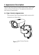
1 Appearance Description There are two kinds of thermal network bullet cameras: Type I bullet camera, and Type II bullet camera. The appearance description of two cameras are shown below. 1.
Sun Shield Camera Memory Card Slot Bracket Holder Cable Outlet Bracket Hinge Bracket Arm Junction Box Cover Reset Button Junction Box Base Sealing Interface Type I Camera Components Overview 1.
Sun Shield Bracket Lens Reset Button Memory Card Slot Camera Components and Cables 1.3 Cable Description The bullet camera cables, including power cable, coaxial video cable, alarm cable, and audio cable are shown below. The Type I camera supports network cable and optical fiber. The Type II camera supports network cable.
Cable Description Name Description Power Interface 24V AC and 12V DC are supported. For 12V DC power supply, make sure that the positive/negative terminals are connected correctly. Network Interface Connect to the LAN interface. PoE+ is supported for type II camera. Use switch that supports PoE+ function. Alarm Interface Two-way alarm input and alarm output are supported. Alarm In: IN1 and G/IN2 and G, Alarm Out: 1A and 1B/2A and 2B.
After the power on of the camera, you must still press and hold the Reset button for about 10 seconds.
2 Installation Before you start: ● Make sure the device in the package is in good condition and all the assembly parts are included. ● The standard power supply is 12V DC or 24V AC, please make sure your power supply matches your camera. ● Make sure all the related equipment is power-off during the installation. ● Check the specification for the installation environment. ● Make sure that the wall is strong enough to withstand eight times the weight of the camera and the bracket.
2.1 Memory Card Installation Make sure you install the memory card in the same way you disassemble the camera, so that the leak-free sealing performance will not be affected. 2.1.1 Type I Camera Memory Card Installation Steps: 1. Unscrew the memory card slot cover and remove it. SD CARD Memory Card Cover Removing Card Slot Cover (Type I Camera) 2. Insert the memory card into the memory card slot.
Memory Card Inserting Memory Card (Type I Camera) 3. Cover the memory card slot and fix the screws on the memory card slot cover. 2.1.2 Type II Camera Memory Card Installation Steps: 1. Unscrew the memory card slot cover and remove it. Memory Card Slot Cover Removing Card Slot Cover (Type II Camera) A rubber seal ring is on the top of the memory card slot cover. Do NOT lose the ring for the waterproof performance.
2. Insert the memory card into the memory card slot. Inserting Memory Card (Type II Camera) 3. Cover the memory card slot and fix the screws on the memory card slot cover.
2.2 Wide Range Coverage for Different Specifications For fixed lens camera, the auto-focus function, and remote manual focus function are not supported.
2.3 Installing Camera 2.3.1 Installing Type I Camera Before you start: There are three methods of Type I camera installation: wall mounting, ceiling mounting, and stand mounting. Wall Mounting Ceiling Mounting Stand Mounting Type I Camera Installation Methods Steps: 1. Loosen the screws on the junction box cover. 2. Draw the latches from the latch hole of the junction box and take apart the cover from the junction box.
3. Attach the drill template (supplied) to the place where you want to fix the camera, and then drill four screw holes (recommended depth: 40mm) in the ceiling/wall according to the drill template. 4. Drill a cable hole according to the A mark of the drill template. Ф10 mm (0.39'') Ф24 mm (0.94'') Drill Template (Type I Camera) 5. Align the hole of drill template with the screw hole of the junction box base to place the junction box onto the wall. 6.
7. Route the cables through the cable hole. 8. Insert the latches into the latch holes to fix the bracket and camera with the junction box. Wall Mounting Ceiling Mounting Stand Mounting Installing Junction Box Cover 9. Fix the delivered screws to secure the junction box. 10. Connect the corresponding cables to power on the camera and get the live view. 11. Adjust the camera according to the figure below.
1. Attach the drill template (supplied) to the place where you want to fix the camera, and then drill the screw holes in the ceiling/wall according to the drill template. 2. (Optional) If you want to route cables through the installation surface, drill a cable hole according to the drill template. Otherwise, skip the step if you route the cable via the side opening. Φ88.5mm (3.48″) Φ5mm (0.20″) Φ36mm (1.42″) Drill Template (Type II Camera) 3. (Optional) Fix the camera to the junction box.
Drill Template 3) Make sure the Top are on the top and the bottom are at the bottom. Fix the junction box to the installation surface with the supplied screws. 4) Fix the bullet camera to the junction box with the supplied screws, as shown in Figure 2-14.
4. Fix the bullet camera to the installation surface with the supplied screws, as shown in Figure 2-15. Wall Mounting Ceilling Mounting Install the Bracket onto the Wall 5. Adjust the camera to the optimal surveillance angle. Bracket type I: 1) Loosen the pan adjusting screw to adjust panning position [0° to 360°]. Tighten the screw. 2) Loosen the tile adjusting screw to adjust the tilting position [0° to 100°]. Tighten the screw.
Bracket type II: 1) Loosen the screw to adjust the tilting position [0° to 90°]. Tighten the screw. 2) Loosen the screw to adjust the rotation position [0° to 360°]. Tighten the screw. Screw 2-axis Adjustment Please loosen the screws slightly until you can adjust the camera. Do NOT remove the screws from the bracket.
Installation of Network Cable Water-proof Jacket Purpose: If the camera is installed outdoor, you can adapt the water-proof accessory for the network cable after the camera is secured on the installation surface. ① ② ③ ④ ⑤ ⑥ Water-proof Accessory Components Table 2-1 Components No.
Align the snap and notch. i. Insert ⑤ into ④. ii. Secure ⑥ with ④. Camera Switch/ Router Water-proof Accessory Installation Steps: 1. Feed the plugless network cable ⑦ through the lock nut ⑥, waterproof rubber gasket ⑤ (rubber gasket inset ridge must face waterproof endcap), and the water-proof endcap ④ in order. 2. Crimp an RJ-45 network plug ③ onto the end of the cable, taking care to insert the twisted pairs of wires in correct order.
3. Place the O-type gasket ② onto the end of the camera’s network interface socket ①. 4. Insert the network plug ③ into the camera’s network interface socket ①. 5. Insert the water-proof rubber gasket ⑤ into the waterproof endcap ④, and secure lock nut ⑥ with the water-proof endcap ④. 6. Align the snap on the water-proof endcap ④ with the notch on the camera’s network interface socket ①, and then secure the water-proof endcap ④ to the camera’s network interface socket ① to finish installation.
3 Setting the Network Camera over the LAN Note: You shall acknowledge that the use of the product with Internet access might be under network security risks. For avoidance of any network attacks and information leakage, please strengthen your own protection. If the product does not work properly, please contact with your dealer or the nearest service center. 3.
3.2 Activating the Camera You are required to activate the camera first by setting a strong password for it before you can use the camera. Activation via Web Browser, Activation via SADP, and Activation via Client Software are all supported. We will take activation via SADP software and Activation via Web Browser as examples to introduce the camera activation. Please refer to the User Manual of Network Camera for Activation via Client Software. 3.2.1 Activation via Web Browser Steps: 1.
Activation Interface(Web) 3. Create a password and input the password into the password field. STRONG PASSWORD RECOMMENDED– We highly recommend you create a strong password of your own choosing (using a minimum of 8 characters, including upper case letters, lower case letters, numbers, and special characters) in order to increase the security of your product.
Select inactive device. Input and confirm password. SADP Interface Note: The SADP software supports activating the camera in batch. Please refer to the user manual of SADP software for details. 3. Create a password and input the password in the password field, and confirm the password.
STRONG PASSWORD RECOMMENDED– We highly recommend you create a strong password of your own choosing (using a minimum of 8 characters, including upper case letters, lower case letters, numbers, and special characters) in order to increase the security of your product. And we recommend you reset your password regularly, especially in the high security system, resetting the password monthly or weekly can better protect your product. 4. Click OK to save the password.
Note: Please refer to Chapter 3.2 to activate the camera if the camera is inactive. 3. Change the device IP address to the same subnet with your computer by either modifying the IP address manually or checking the checkbox of Enable DHCP.
4. Input the password to activate your IP address modification. The batch IP address modification is supported by the SADP; please refer to the User Manual of SADP for details.
4 Accessing via Web Browser System Requirement: Operating System: Microsoft Windows XP SP1 and above version CPU: 2.0 GHz or higher RAM: 1G or higher Display: 1024×768 resolution or higher Web Browser: Internet Explorer 8.0 and above version, Apple Safari 5.0.2 and above version, Mozilla Firefox 5.0 and above version and Google Chrome 18 and above version Steps: 1. Open the web browser. 2.
Login Interface 5. Install the plug-in before viewing the live video and managing the camera. Please follow the installation prompts to install the plug-in. You may have to close the web browser to finish the installation of the plug-in. Download Plug-in 6. Reopen the web browser after the installation of the plug-in and repeat steps 2~4 to login.
For detailed instructions of further configuration, please refer to the user manual of network camera.
Appendix Frequently Asked Questions (FAQ) Device Running Error Question: The device fails to start up or reboots repeatedly. Answer: Examine the power supply of the positioning system and see whether it meets the requirements. Select the power supply as close as possible. Examine the power cord and see whether it meets the requirements. Device Upgrading Question: Device fails to upgrade. Answer: Examine if the device upgrading fails because of the poor network.
Examine if the lens is dirty or not. Examine if any obstruction is nearby, e.g. spider web. Question: Live view fails with good network connection. Answer: Examine if the IE plug-in is well installed. Change the Website Blocker settings if necessary. For cross-domain routing, enable the UPnP of device, or set manual mapping to port No. 80, 8000, or 554. Examine if the live view channel amount exceeds the upper limit. Examine the network bandwidth.
Common Material Emissivity Reference Material Emissivity Human Skin 0.98 PCB 0.91 Cement Concrete 0.95 Ceramics 0.92 Rubber 0.95 Paint 0.93 Wood 0.85 Asphalt 0.96 Brick 0.95 Sand 0.90 Soil 0.92 Cotton 0.98 Cardboard 0.90 White Paper 0.90 Water 0.
[0] UD13140B