
User Manual
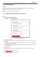
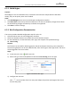
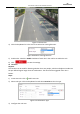
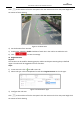
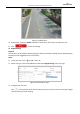
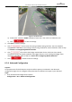
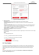
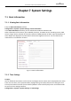
Table Of Contents
- About This Document
- Chapter 1 Activating and Accessing to the Camera
- Chapter 2 Setting Local Parameters and Network
- Chapter 3 Live View
- Chapter 4 PTZ Control
- 4.1 Operating PTZ Control
- 4.2 PTZ Configuration
- 4.2.1 Configuring Basic PTZ Parameters
- 4.2.2 Configuring PTZ Limits
- 4.2.3 Configuring Initial Position
- 4.2.4 Configuring Park Action
- 4.2.5 Configuring Privacy Mask
- 4.2.6 Configuring Scheduled Tasks
- 4.2.7 Clearing PTZ Configurations
- 4.2.8 Configuring PTZ Control Priority
- 4.2.9 Configuring Panorama Tracking
- 4.2.10 Rapid Focus
- Chapter 5 Storage and Playback
- Chapter 6 Events Settings
- Chapter 7 System Settings
- Appendix
- Appendix 1 SADP Software Introduction
- Appendix 2 Statics, Interference Lightning and Surge Protection
- Appendix 3 Waterproof
- Appendix 4 Bubble Maintenance
- Appendix 5 RS-485 Bus Connection
- Appendix 6 24VAC Wire Gauge & Transmission Distance
- Appendix 7 12VDC Wire Gauge & Transmission Distance
- Appendix 8 Table of Wire Gauge Standards
- Appendix 9 Alarm In/Out Connections
- Appendix 10 Camera Function Description

User Manual of PanoVu Series Network Camera
85
6.3.2 Shield Region
Purpose:
Shield Region is the user-defined areas in surveillance scene that the analysis doesn't take effect.
Usually, they can be privacy areas. Set if needed.
Steps:
1. Click Shield Region tab to enter the shield region configuration interface
2. Click Draw Area. Draw area by left click end-points in the live view window, and right click to finish
the area drawing. Polygon area with up to 10 sides are supported.
3. Click Save to save the settings.
6.3.3 Rule Configuration Demonstration
This section provides detailed configuration steps for each rule.
1. Click Rule Tab to enter the rule configuration interface.
2. Check the checkbox in Rule List to enable the rule for behavior analysis.
3. For the selected rule, set the Rule Name, Rule Type, and complete rule-specified settings.
Line Crossing
Purpose:
This function can be used for detecting people, vehicles and objects traversing a set virtual plane.
The traversing direction can be set as bidirectional, from left to right or from right to left. The alarm
will be triggered if the rule is broken.
Steps:
1) Create new rule: Click add a new rule.
2) Select rule type: Click the dropdown list and select Line Crossing as the rule type.
Figure 6-18 Select Rule Type
3) Configure the rule area:
Click on the tool bar of the live view panel. Adjust the position and length of the line on
the live view panel.