
User Manual
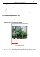
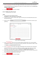
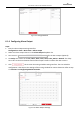
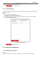
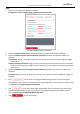
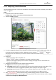
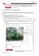
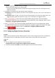
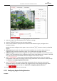
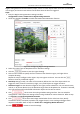
Table Of Contents
- About This Document
- Chapter 1 Activating and Accessing to the Camera
- Chapter 2 Setting Local Parameters and Network
- Chapter 3 Live View
- Chapter 4 PTZ Control
- 4.1 Operating PTZ Control
- 4.2 PTZ Configuration
- 4.2.1 Configuring Basic PTZ Parameters
- 4.2.2 Configuring PTZ Limits
- 4.2.3 Configuring Initial Position
- 4.2.4 Configuring Park Action
- 4.2.5 Configuring Privacy Mask
- 4.2.6 Configuring Scheduled Tasks
- 4.2.7 Clearing PTZ Configurations
- 4.2.8 Configuring PTZ Control Priority
- 4.2.9 Configuring Panorama Tracking
- 4.2.10 Rapid Focus
- Chapter 5 Storage and Playback
- Chapter 6 Events Settings
- Chapter 7 System Settings
- Appendix
- Appendix 1 SADP Software Introduction
- Appendix 2 Statics, Interference Lightning and Surge Protection
- Appendix 3 Waterproof
- Appendix 4 Bubble Maintenance
- Appendix 5 RS-485 Bus Connection
- Appendix 6 24VAC Wire Gauge & Transmission Distance
- Appendix 7 12VDC Wire Gauge & Transmission Distance
- Appendix 8 Table of Wire Gauge Standards
- Appendix 9 Alarm In/Out Connections
- Appendix 10 Camera Function Description

User Manual of PanoVu Series Network Camera
82
Figure 6-15 Configuring Region Entrance Detection
3. Select the region from the dropdown list for detection settings.
4. Click the button to start the region drawing.
5. Click on the live video to specify the four vertexes of the detection region, and right click to
complete drawing.
Repeat the step to configure other regions. You can click the button to clear all pre-defined
regions.
6. Sensitivity: Range [1-100]. The value of the sensitivity defines the size of the object which can
trigger the alarm, when the sensitivity is high, a very small object can trigger the alarm.
7. Detection Target: Set the detection target for the region entrance detection. You can select human,
vehicle, or all (human &vehicle) as the detection target from the dropdown list. If Human is selected,
only human beings will be identified as detection objects and as well as Vehicle.
8. Click tab to enter the arming schedule setting interface. The time schedule
configuration is the same as the settings of the arming schedule for motion detection. Refer to Step
5 in Section 6.1.1 Configuring Motion Detection.
9. Click tab to select the linkage method taken for the video loss alarm, Notify
surveillance center, send email, upload to FTP, trigger channel, smart tracking and trigger alarm
output are selectable. Refer to Step 3 in Section 6.1.1 Configuring Motion Detection.
10. Click to save the settings.
6.2.5 Configuring Region Exiting Detection
Purpose: