
User Manual
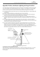
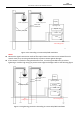
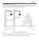
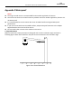
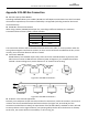
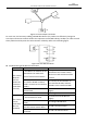
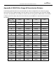
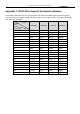
Table Of Contents
- About This Document
- Chapter 1 Activating and Accessing to the Camera
- Chapter 2 Setting Local Parameters and Network
- Chapter 3 Live View
- Chapter 4 PTZ Control
- 4.1 Operating PTZ Control
- 4.2 PTZ Configuration
- 4.2.1 Configuring Basic PTZ Parameters
- 4.2.2 Configuring PTZ Limits
- 4.2.3 Configuring Initial Position
- 4.2.4 Configuring Park Action
- 4.2.5 Configuring Privacy Mask
- 4.2.6 Configuring Scheduled Tasks
- 4.2.7 Clearing PTZ Configurations
- 4.2.8 Configuring PTZ Control Priority
- 4.2.9 Configuring Panorama Tracking
- 4.2.10 Rapid Focus
- Chapter 5 Storage and Playback
- Chapter 6 Events Settings
- Chapter 7 System Settings
- Appendix
- Appendix 1 SADP Software Introduction
- Appendix 2 Statics, Interference Lightning and Surge Protection
- Appendix 3 Waterproof
- Appendix 4 Bubble Maintenance
- Appendix 5 RS-485 Bus Connection
- Appendix 6 24VAC Wire Gauge & Transmission Distance
- Appendix 7 12VDC Wire Gauge & Transmission Distance
- Appendix 8 Table of Wire Gauge Standards
- Appendix 9 Alarm In/Out Connections
- Appendix 10 Camera Function Description

User Manual of PanoVu Series Network Camera
111
1#
6#
15#
32#
Controller
Figure A.6.3 Star Shape Connection
For such case, the best way is adding a RS-485 distributor. This product can effectively change the
star-shape connection to which satisfies the requirement of RS-485 industry standard, in order to avoid
those problems and improve the communication reliability. Refer to the following figure.
A+
B-
RS485 Distributor
120Ω
1#
2#
16#
120Ω
120Ω
Figure A.6.4 RS-485 Distributor
Troubleshooting of RS-485 communication
Problem
Possible Reasons
To Solve the Problem
The camera
does the
self-test
action but
cannot be
controlled
remotely.
1. The address or baudrate of the
camera does not match with
those of remote control device.
1. Adjust the address and
baudrate of the remote control
device to match with those of the
camera.
2. The wire RS-485+ connects to
the interface RS-485- and wire
RS-485- connects to the interface
RS-485+.
2. Connect the wire RS-485+ to
the interface RS-485+ and wire
RS-485- to the interface RS-485-.
3. The RS-485 wire is
disconnected.
3. Reconnect the RS-485 wire
tightly.
4. RS-485 wire is broken.
4. Change a RS-485 wire.
The camera
can be
controlled
but not
smoothly.
1. The connection is loose.
1. Reconnect the RS-485 wire
tightly.
2. RS-485+ or RS-485-wire is
broken.
2. Change a RS-485 wire.
3. The camera is too far away
from the remote control device.
3. Add a terminal resistor.
4. Too many cameras are
connected.
4. Add a RS-485 distributor.