
Operation Manual
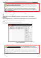

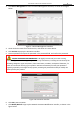
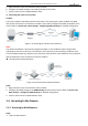

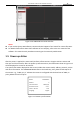

Table Of Contents
- About This Document
- Chapter 1 Activating and Accessing to the Camera
- Chapter 2 Setting Local Parameters and Network
- Chapter 3 Live View
- Chapter 4 PTZ Control
- 4.1 Operating PTZ Control
- 4.2 PTZ Configuration
- 4.2.1 Configuring Basic PTZ Parameters
- 4.2.2 Configuring PTZ Limits
- 4.2.3 Configuring Initial Position
- 4.2.4 Configuring Park Action
- 4.2.5 Configuring Privacy Mask
- 4.2.6 Configuring Scheduled Tasks
- 4.2.7 Clearing PTZ Configurations
- 4.2.8 Configuring PTZ Control Priority
- 4.2.9 Configuring Panorama Tracking
- 4.2.10 Configuring Eagle Vision Focus
- Chapter 5 Storage and Playback
- Chapter 6 Alarm and Events
- 6.1 Basic Event Configuration
- 6.2 Smart Event Configuration
- 6.3 VCA Configuration
- Chapter 7 Maintenance
- Appendix
- Appendix 1 SADP Software Introduction
- Appendix 2 Statics, Interference Lightning and Surge Protection
- Appendix 3 Waterproof
- Appendix 4 Bubble Maintenance
- Appendix 5 RS-485 Bus Connection
- Appendix 6 24VAC Wire Gauge & Transmission Distance
- Appendix 7 12VDC Wire Gauge & Transmission Distance
- Appendix 8 Table of Wire Gauge Standards
- Appendix 9 Alarm In/Out Connections
- Appendix 10 Camera Function Description

User Manual of PanoVu Series Network Camera
11
Figure 1-16 iVMS-4200 Live View Interface
Notes:
If you use third party VMS software, contact technical support of our branch for camera firmware.
For detailed information about client software of our company, refer to the user manual of the
software. This manual mainly introduces accessing to the camera by web browser.
1.5 Power-up Action
After the power is applied, the camera will perform self-test actions. It begins with lens actions and
then pan and tilt movement. After the power-up self-test actions, the information shown in Figure 1-17
will be displayed on screen for 40 seconds.
The system information displayed on the screen includes the camera model, address, protocol, version
and other information. The COMMUNICATION refers to the baud rate, parity, data bit and stop bit of
the camera. e.g., “2400, N, 8, 1” indicates the camera is configured with the baud rate of 2400, no
parity, 8 data bits and 1 stop bit.
Model XX-XXXXXX-X
Address 0
Communication 0000,0,0,0
Software Version Vx.x.x
Camera Version Vx.xx
Language English
Figure 1-17 Power-up Information