
Operation Manual
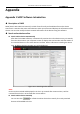
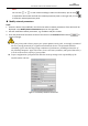
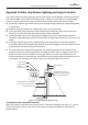

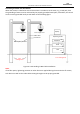
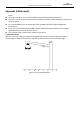


Table Of Contents
- About This Document
- Chapter 1 Activating and Accessing to the Camera
- Chapter 2 Setting Local Parameters and Network
- Chapter 3 Live View
- Chapter 4 PTZ Control
- 4.1 Operating PTZ Control
- 4.2 PTZ Configuration
- 4.2.1 Configuring Basic PTZ Parameters
- 4.2.2 Configuring PTZ Limits
- 4.2.3 Configuring Initial Position
- 4.2.4 Configuring Park Action
- 4.2.5 Configuring Privacy Mask
- 4.2.6 Configuring Scheduled Tasks
- 4.2.7 Clearing PTZ Configurations
- 4.2.8 Configuring PTZ Control Priority
- 4.2.9 Configuring Panorama Tracking
- 4.2.10 Configuring Eagle Vision Focus
- Chapter 5 Storage and Playback
- Chapter 6 Alarm and Events
- 6.1 Basic Event Configuration
- 6.2 Smart Event Configuration
- 6.3 VCA Configuration
- Chapter 7 Maintenance
- Appendix
- Appendix 1 SADP Software Introduction
- Appendix 2 Statics, Interference Lightning and Surge Protection
- Appendix 3 Waterproof
- Appendix 4 Bubble Maintenance
- Appendix 5 RS-485 Bus Connection
- Appendix 6 24VAC Wire Gauge & Transmission Distance
- Appendix 7 12VDC Wire Gauge & Transmission Distance
- Appendix 8 Table of Wire Gauge Standards
- Appendix 9 Alarm In/Out Connections
- Appendix 10 Camera Function Description

User Manual of PanoVu Series Network Camera
111
Appendix 5 RS-485 Bus Connection
General Property of RS-485 Bus
According to RS-485 industry bus standard, RS-485 is a half-duplex communication bus which has 120Ω
characteristic impendence, the maximum load ability is 32 payloads (including controller device and
controlled device).
RS-485 Bus Transmission Distance
When using 0.56mm (24AWG) twisted-pair line, according to different baudrate, the maximum
transmission distance theory table is shown as below:
Max. Distance of RS-485 Transmission
Baudrate
Max Distance
2400BPS
1800m
4800BPS
1200m
9600BPS
800m
The transmission distance will be decreased if we use the thinner cable, or use this product under the
strong electromagnetic interference situation, or there are lots of devices are added to the bus; on the
contrary, the transmission distance will be increased.
Connection Methods
RS-485 industry bus standard require daisy-chain connection method between any devices, both
sides have to connect a 120Ω terminal resistance (show as Diagram 1), the simplified connection
method is shown as diagram 2, but the distance of “D” should not be too long.
1#
2#
3#
32#
…
120Ω
120Ω
Figure A.6.1 RS-485 Connection 1
…
Controller
A+
B-
1#
2# 31#
A+ B-
D
Figure A.6.2 RS-485 Connection 2
Problems in the Practical Application
Normally, users adopt star-shape connection method in construction, under this situation, the terminal
resistors must be connected between two farthest devices (as Figure A-9, 1# and 15#), but this
connection method is not satisfy the requirement of the RS-485 industry standard so that it will lead to
some problems such as signal reflection, anti-jamming ability decline when the devices are faraway. At
this time, the camera will be uncontrollable, or self-running, etc.