
Operation Manual
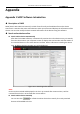
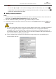
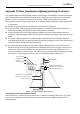

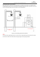
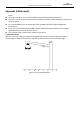


Table Of Contents
- About This Document
- Chapter 1 Activating and Accessing to the Camera
- Chapter 2 Setting Local Parameters and Network
- Chapter 3 Live View
- Chapter 4 PTZ Control
- 4.1 Operating PTZ Control
- 4.2 PTZ Configuration
- 4.2.1 Configuring Basic PTZ Parameters
- 4.2.2 Configuring PTZ Limits
- 4.2.3 Configuring Initial Position
- 4.2.4 Configuring Park Action
- 4.2.5 Configuring Privacy Mask
- 4.2.6 Configuring Scheduled Tasks
- 4.2.7 Clearing PTZ Configurations
- 4.2.8 Configuring PTZ Control Priority
- 4.2.9 Configuring Panorama Tracking
- 4.2.10 Configuring Eagle Vision Focus
- Chapter 5 Storage and Playback
- Chapter 6 Alarm and Events
- 6.1 Basic Event Configuration
- 6.2 Smart Event Configuration
- 6.3 VCA Configuration
- Chapter 7 Maintenance
- Appendix
- Appendix 1 SADP Software Introduction
- Appendix 2 Statics, Interference Lightning and Surge Protection
- Appendix 3 Waterproof
- Appendix 4 Bubble Maintenance
- Appendix 5 RS-485 Bus Connection
- Appendix 6 24VAC Wire Gauge & Transmission Distance
- Appendix 7 12VDC Wire Gauge & Transmission Distance
- Appendix 8 Table of Wire Gauge Standards
- Appendix 9 Alarm In/Out Connections
- Appendix 10 Camera Function Description

User Manual of PanoVu Series Network Camera
109
Appendix 3 Waterproof
Notes:
The long-arm wall mount is recommended for the outdoor application of camera.
You cannot use the short-arm wall mount or pendant mount for outdoor application, because it is
not water-proof.
It is recommended to use the mount with inner threaded interface and good waterproof
performance.
If you use a mount with outer threaded interface, adopt waterproof measures to the adapter
applied between the mount and the camera.
Do not install indoor camera to the outdoor environment.
L-shape Pole Mount
Make sure that the L-shape pole mount is designed with a certain inclination angle as shown in
following figure. Water won’t flow from the pole into the camera with the inclination angle.
θ
Figure A.4.1 Customized Mount