
User Manual
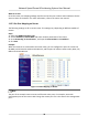
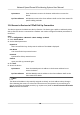
Table Of Contents
- Legal Information
- Chapter 1 Overview
- Chapter 2 Device Activation and Accessing
- Chapter 3 Face Capture
- Chapter 4 Road Traffic
- Chapter 5 PTZ
- Chapter 6 Live View
- 6.1 Live View Parameters
- 6.1.1 Start and Stop Live View
- 6.1.2 Aspect Ratio
- 6.1.3 Live View Stream Type
- 6.1.4 Quick Set Live View
- 6.1.5 Select the Third-Party Plug-in
- 6.1.6 Start Digital Zoom
- 6.1.7 Conduct Regional Focus
- 6.1.8 Conduct Regional Exposure
- 6.1.9 Count Pixel
- 6.1.10 Light
- 6.1.11 Operate Wiper
- 6.1.12 Lens Initialization
- 6.1.13 Track Manually
- 6.1.14 Conduct 3D Positioning
- 6.2 Set Transmission Parameters
- 6.3 Smart Display
- 6.1 Live View Parameters
- Chapter 7 Video and Audio
- Chapter 8 Video Recording and Picture Capture
- Chapter 9 Event and Alarm
- Chapter 10 Arming Schedule and Alarm Linkage
- Chapter 11 Network Settings
- 11.1 TCP/IP
- 11.2 Port
- 11.3 Port Mapping
- 11.4 SNMP
- 11.5 Access to Device via Domain Name
- 11.6 Access to Device via PPPoE Dial Up Connection
- 11.7 Accessing via Mobile Client
- 11.8 Set ISUP
- 11.9 Set Open Network Video Interface
- 11.10 Set Network Service
- 11.11 Set Alarm Server
- 11.12 TCP Acceleration
- 11.13 Traffic Shaping
- 11.14 Set SRTP
- Chapter 12 System and Security
- 12.1 View Device Information
- 12.2 Restore and Default
- 12.3 Search and Manage Log
- 12.4 Import and Export Configuration File
- 12.5 Export Diagnose Information
- 12.6 Reboot
- 12.7 Upgrade
- 12.8 eMMC Protection
- 12.9 View Open Source Software License
- 12.10 Set Live View Connection
- 12.11 Time and Date
- 12.12 Set RS-485
- 12.13 Security
- Appendix A. Device Command
- Appendix B. Device Communication Matrix

What to do next
Go to the router port mapping sengs interface and set the port number and IP address to be the
same as those on the device. For more informaon, refer to the router user manual.
11.3.3 Set Port Mapping on Router
The following sengs are for a certain router. The sengs vary depending on dierent models of
routers.
Steps
1. Select the WAN Connecon Type.
2. Set the IP Address, Subnet Mask and other network parameters of the router.
3. Go to Forwarding → Virtual Severs , and input the Port Number and IP Address.
4. Click Save.
Example
When the cameras are connected to the same router, you can
congure the ports of a camera as
80, 8000, and 554 with IP address 192.168.1.23, and the ports of another camera as 81, 8001, 555,
8201 with IP 192.168.1.24.
Figure 11-1 Port Mapping on Router
Note
The port of the network camera cannot conict with other ports. For example, some web
management port of the router is 80. Change the camera port if it is the same as the management
port.
Network Speed Dome & Posioning System User Manual
78