
User Manual
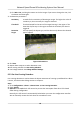
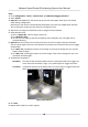
Table Of Contents
- Legal Information
- Chapter 1 Overview
- Chapter 2 Device Activation and Accessing
- Chapter 3 Face Capture
- Chapter 4 Road Traffic
- Chapter 5 PTZ
- Chapter 6 Live View
- 6.1 Live View Parameters
- 6.1.1 Start and Stop Live View
- 6.1.2 Aspect Ratio
- 6.1.3 Live View Stream Type
- 6.1.4 Quick Set Live View
- 6.1.5 Select the Third-Party Plug-in
- 6.1.6 Start Digital Zoom
- 6.1.7 Conduct Regional Focus
- 6.1.8 Conduct Regional Exposure
- 6.1.9 Count Pixel
- 6.1.10 Light
- 6.1.11 Operate Wiper
- 6.1.12 Lens Initialization
- 6.1.13 Track Manually
- 6.1.14 Conduct 3D Positioning
- 6.2 Set Transmission Parameters
- 6.3 Smart Display
- 6.1 Live View Parameters
- Chapter 7 Video and Audio
- Chapter 8 Video Recording and Picture Capture
- Chapter 9 Event and Alarm
- Chapter 10 Arming Schedule and Alarm Linkage
- Chapter 11 Network Settings
- 11.1 TCP/IP
- 11.2 Port
- 11.3 Port Mapping
- 11.4 SNMP
- 11.5 Access to Device via Domain Name
- 11.6 Access to Device via PPPoE Dial Up Connection
- 11.7 Accessing via Mobile Client
- 11.8 Set ISUP
- 11.9 Set Open Network Video Interface
- 11.10 Set Network Service
- 11.11 Set Alarm Server
- 11.12 TCP Acceleration
- 11.13 Traffic Shaping
- 11.14 Set SRTP
- Chapter 12 System and Security
- 12.1 View Device Information
- 12.2 Restore and Default
- 12.3 Search and Manage Log
- 12.4 Import and Export Configuration File
- 12.5 Export Diagnose Information
- 12.6 Reboot
- 12.7 Upgrade
- 12.8 eMMC Protection
- 12.9 View Open Source Software License
- 12.10 Set Live View Connection
- 12.11 Time and Date
- 12.12 Set RS-485
- 12.13 Security
- Appendix A. Device Command
- Appendix B. Device Communication Matrix

4. Adjust the live image to the desired scene by using PTZ control
buons.
5. Draw detecon line.
1) Select a Line No.. Up to 4 lines can be set in the scene.
2) Click Detecon Area.
A yellow line is displayed on live image.
3) Click on the line, and drag its end points to adjust the length and
posion.
4) Select the Direcon for the detecon line.
Direcon
It stands for the direcon from which the object goes across the line.
A<->B
The object going across the line from both direcons can be detected and alarms are
triggered.
A->B
Only the object crossing the
congured line from side A to side B can be detected.
B->A
Only the object crossing the congured line from side B to side A can be detected.
Figure 9-5 Draw Line
6. Oponal: Set the minimum size and the maximum size for the target to improve detecon
accuracy. Only targets whose size are between the maximum size and the minimum size trigger
the detecon.
1) Click Max. Size, and drag the mouse on live image. If you want to change the size, click the
buon and draw again.
2) Click Min. Size, and drag the mouse on the live image. If you want to change the size, click
the
buon and draw again.
7. Set detecon parameters.
Sensivity
It stands for the sensivity of detecng an target. The higher the value is,
the more easily the target is detected.
Network Speed Dome & Posioning System User Manual
63