
Quick Start Guide
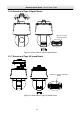
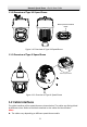
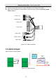
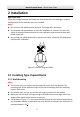
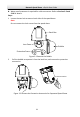
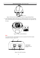
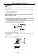
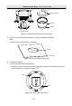
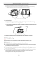
Table Of Contents
- 1 Overview
- 1.1 Speed Dome Overview
- 1.1.1 Overview of Type I Speed Dome
- 1.1.2 Overview of Type II Speed Dome
- 1.1.3 Overview of Type III Speed Dome
- 1.1.4 Overview of Type IV Speed Dome
- 1.1.5 Overview of Type V Speed Dome
- 1.1.6 Overview of Type VI Speed Dome
- 1.1.7 Overview of Type VII Speed Dome
- 1.1.8 Overview of Type VIII Speed Dome
- 1.1.9 Overview of Type IX Speed Dome
- 1.2 Cable Interfaces
- 1.3 Alarm Output
- 1.1 Speed Dome Overview
- 2 Installation
- 2.1 Installing Type I Speed Dome
- 2.2 Installing Type II Speed Dome
- 2.3 Installing Type III Speed Dome
- 2.4 Installing Type IV Speed Dome
- 2.5 Installing Type V Speed Dome
- 2.6 Installing Type VI and VII Speed Dome
- 2.7 Installing Type VIII Speed Dome
- 2.8 Installing Type IX Speed Dome
- 2.9 Installation of Network Cable Waterproof Jacket
- 2.10 Installation of Water-proof Tape
- 2.11 Protective Measures for Outdoor Installation
- 3 Activate and Access Network Camera

Network Speed Dome·Quick Start Guide
6
Make sure the speed dome is power-off before you connect the cables.
Water-proof treatment is required for cable connectors. Refer to Section 2.9 and
2.10 for details.
Network Cable
Audio Cable
Alarm Cable
Video Cable
RS-485 Cable
Power Cord
Optical Fiber
Figure 1-12 Cable Interfaces
1.3 Alarm Output
Alarm output is shown below.
Relay Output
OUT (n)
DC
OUT (n)
Direct load
+
-
Relay Output
OUT (n)
OUT (n)
DC 30V
1A
Power Supply
GND Output
~220V AC
FireWire
Zero
Line
JQC-3FG
Relay
(10A 250VAC)
Figure 1-13 Alarm Output