Network Speed Dome Quick Start Guide UD06820B
Network Speed Dome·Quick Start Guide Quick Start Guide COPYRIGHT © 2017 Hangzhou Hikvision Digital Technology Co., Ltd. ALL RIGHTS RESERVED. Any and all information, including, among others, wordings, pictures, graphs are the properties of Hangzhou Hikvision Digital Technology Co., Ltd. or its subsidiaries (hereinafter referred to be “Hikvision”).
Network Speed Dome·Quick Start Guide USE CONFORMS THE APPLICABLE LAW. HIKVISION SHALL NOT BE LIABLE IN THE EVENT THAT THIS PRODUCT IS USED WITH ILLEGITIMATE PURPOSES. IN THE EVENT OF ANY CONFLICTS BETWEEN THIS MANUAL AND THE APPLICABLE LAW, THE LATER PREVAILS.
Network Speed Dome·Quick Start Guide Regulatory Information FCC Information Please take attention that changes or modification not expressly approved by the party responsible for compliance could void the user’s authority to operate the equipment. FCC compliance: This equipment has been tested and found to comply with the limits for a Class A digital device, pursuant to part 15 of the FCC Rules.
Network Speed Dome·Quick Start Guide Safety Instruction These instructions are intended to ensure that user can use the product correctly to avoid danger or property loss. The precaution measure is divided into Warnings and Cautions: Warnings: Neglecting any of the warnings may cause serious injury or death. Cautions: Neglecting any of the cautions may cause injury or equipment damage. Warnings Follow these safeguards to prevent serious injury or death.
Network Speed Dome·Quick Start Guide Do not drop the speed dome or subject it to physical shock, and do not expose it to high electromagnetism radiation. Avoid installation on vibrations surface or places subject to shock (ignorance can cause device damage). Do not touch senor modules with fingers. If cleaning is necessary, use clean cloth with a bit of ethanol and wipe it gently. If the speed dome will not be used for an extended period, replace the lens cap to protect the sensor from dirt.
Network Speed Dome·Quick Start Guide Table of Contents 1 Overview ...................................................................................................... 1 1.1 Speed Dome Overview ............................................................................................ 1 1.1.1 Overview of Type I Speed Dome ....................................................................... 1 1.1.2 Overview of Type II Speed Dome ......................................................................
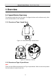
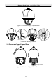
Network Speed Dome·Quick Start Guide 1 Overview 1.1 Speed Dome Overview The network speed dome has five types. The figures below are for reference only, refer to the actual product as the standard. 1.1.1 Overview of Type I Speed Dome Figure 1-1 Overview of Type I Speed Dome Memory Card Slot Figure 1-2 Memory Card Slot 1.1.2 Overview of Type II Speed Dome Note: There are two different appearances of Type II speed dome. Refer to the actual product for the location of memory card slot.
Network Speed Dome·Quick Start Guide Figure 1-3 Overview of Type II Speed Dome Memory Card Slot Debug Reset Memory Card Slot Figure 1-4 Memory Card Slot 1.1.
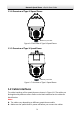
Network Speed Dome·Quick Start Guide 1.1.4 Overview of Type IV Speed Dome Memory Card Slot Figure 1-6 Overview of Type IV Speed Dome 1.1.5 Overview of Type V Speed Dome Memory Card Slot Figure 1-7 Overview of Type V Speed Dome 1.2 Cable Interfaces The cable interfaces of the speed dome are shown in Figure 1-8. The cables are distinguished by different colors. Refer to the labels attached on the cables for identification. Notes: The cables vary depending on different speed dome models.
Network Speed Dome·Quick Start Guide Power Cord RS-485 Cable Alarm Cable Audio Cable Video Cable Network Cable Figure 1-8 Cable Interfaces 1.3 Alarm Output Alarm output is shown in Figure 1-9.
Network Speed Dome·Quick Start Guide 2 Installation Before you start: Check the package contents and make sure that the device in the package is in good condition and all the assembly parts are included. Notes: Do not touch the bubble directly by hand. The image blurs otherwise. Do not power the speed dome up until the installation is finished. To ensure the safety of personnel and equipment, all the installation steps should be done with power supply off.
Network Speed Dome·Quick Start Guide Steps: 1. Loosen the two lock screws on both sides of the speed dome. Note: Do not remove the lock screws from the speed dome. Back Box Lens Cover Bubble Protective Foam Figure 2-2 Remove the Bubble 2. Pull the bubble to separate it from the back box, and remove the protective accessories.
Network Speed Dome·Quick Start Guide 3. If the speed dome supports PoE (Power over Ethernet) function, you can switch the PoE+ and Hi-PoE function for the speed dome. If PoE function is not supported, skip this step. ON 1 2 Figure 2-5 PoE+ and Hi-PoE Switch Note: If you choose Hi-PoE, a Hi-PoE adapter must be connected. The Hi-PoE module connection is shown in Figure 2-6.
Network Speed Dome·Quick Start Guide 6. Install the bracket. 1). Drill four screw holes in the wall according to the holes on the bracket, and then insert four M8 expansion screws into the mounting holes. 2). Attach the gasket and the bracket to the wall by aligning the four screw holes on the bracket with four expansion screws on the wall. 3). Secure the bracket with four hex nuts and washers. Figure 2-7 Secure the Bracket 7. Install the speed dome to the bracket. 1).
Network Speed Dome·Quick Start Guide Lock Screw Lock Screw Figure 2-9 Install the Speed Dome to the Bracket 8. Remove the protective film on the bubble after the installation is finished.. 2.1.2 In-ceiling Mounting Note: In-ceiling mounting is only supported by indoor speed dome models of Type I. Before you start: The height of the space above the ceiling must be more than 250 mm. The thickness of the ceiling must range from 5 mm to 40 mm.
Network Speed Dome·Quick Start Guide 5. Drill a hole on the ceiling according to the drill template (supplied). Note: ±2 mm of the circle diameter is tolerable. Φ 224 Unit: mm Figure 2-11 Drill a Hole on the Ceiling 6. Connect the cables. 7. Install the speed dome to the ceiling. 1). Loosen the two lock screws on both sides of the back box and make the locks in internal position as shown in Figure 2-12. Lock Lock Figure 2-12 Locks and Lock Screws 2).
Network Speed Dome·Quick Start Guide 1). Attach the flange to the bubble and align the triangular notch of the trim ring with the arrow label on the in-ceiling bracket. 2). Firmly place the flange to the ceiling, and rotate the flange in the direction of the arrow to secure it. Arrow Label Notch Figure 2-14 Install the Flange 9. Remove the protective film on the bubble after the installation is finished. 2.1.3 Ceiling Mounting Note: Ceiling mounting is only supported by indoor speed dome models of Type I.
Network Speed Dome·Quick Start Guide 2). Remove the in-ceiling bracket as shown in Figure 2-16. Figure 2-16 Remove the Bracket 3). Install four bolts to the screw holes as shown in Figure 2-17. Figure 2-17 Install the bolts 2. Route the cables. The cables of speed dome can be routed either from the top or the side of the back box, as shown in Figure 2-18. For the cables routed from the top of the back box, it is required to drill a cable hole in the ceiling. Figure 2-18 Cabling for Ceiling Mounting 3.
Network Speed Dome·Quick Start Guide 3). Attach the bubble to the back box, and rotate clockwise to secure it. 4). Use the mounting base as a template to mark four screw holes onto the ceiling. 5). If you route cables from the top of the back box, mark the cable hole on the ceiling and drill a hole. 6). Secure the mounting base to the ceiling with the set screws. Screw Holes Cable Hole Figure 2-19 Secure the Mounting Base 7). Route the cables for the speed dome.
Network Speed Dome·Quick Start Guide 2.2 Installing Type II Speed Dome Wall Mounting Notes: For cement wall, you need to use the expansion screw to fix the bracket. The mounting hole of the expansion pipe on the wall should align with the mounting hole on the bracket. For wooden wall, you can just use the self-tapping screw to fix the bracket. Make sure that the wall is strong enough to withstand more than eight times the weight of the speed dome and the accessories.
Network Speed Dome·Quick Start Guide 3. Install the memory card. Debug Reset Memory Card Slot Open Cover Memory Card Slot Figure 2-23 Install the Memory Card. 4. Align the cuts on the bubble with the lock screws on the back box to reinstall the bubble. Tighten the lock screws. 5. Refer to steps 6 in section 2.1.1 Wall Mounting to install the bracket. 6. Install the speed dome to the bracket. 1). Hook the back box of the speed dome to the bracket with the safety rope.
Network Speed Dome·Quick Start Guide Lock Screw Figure 2-25 Install the Speed Dome to the Bracket 7. Remove the protective film on the bubble after the installation is finished. 2.3 Installing Type III Speed Dome Wall Mounting Notes: For cement wall, you need to use the expansion screw to fix the bracket. The mounting hole of the expansion pipe on the wall should align with the mounting hole on the bracket. For wooden wall, you can just use the self-tapping screw to fix the bracket.
Network Speed Dome·Quick Start Guide Protective Sticker Figure 2-26 Remove Protective Sticker 2. Remove the cover on the back of speed dome as shown in Figure 2-27. Insert the memory card to the memory card slot and install the cover back. SD CARD Memory Card Slot Figure 2-27 Memory Card Slot 3. Refer to steps 6 in section 2.1.1 Wall Mounting to install the bracket. 4. Hook the two ends of the safety rope to the speed dome back box and the bracket respectively. Route the cables through the bracket.
Network Speed Dome·Quick Start Guide Safety Rope Figure 2-28 Install the Safety Rope 5. Loosen the lock screws on the bracket. 6. Align the speed dome with bracket and rotate it counterclockwise or clockwise to the bracket tightly as shown in Figure 2-29. Figure 2-29 Install the Speed dome 7. Use the wrench to tighten the lock screws to secure the speed dome and the bracket.
Network Speed Dome·Quick Start Guide Figure 2-30 Secure the Speed dome 8. Remove the protective film on the bubble after the installation is finished. 2.4 Installing Type IV Speed Dome Wall Mounting Notes: For cement wall, you need to use the expansion screw to fix the bracket. The mounting hole of the expansion pipe on the wall should align with the mounting hole on the bracket. For wooden wall, you can just use the self-tapping screw to fix the bracket.
Network Speed Dome·Quick Start Guide Protective Sticker Figure 2-31 Remove Protective Sticker 2. Remove the cover on the back of speed dome as shown in Figure 2-32. Insert the memory card to the memory card slot and install the cover back. Memory Card Slot Figure 2-32 Memory Card Slot 3. Secure the bracket with four hex nuts and washers. Figure 2-33 Secure the Bracket 4. Apply thread tape to the thread of the head cover and rotate the head cover to the bracket.
Network Speed Dome·Quick Start Guide Figure 2-34 Secure the Head Cover 5. Buckle the handle to the safety rope. + Figure 2-35 Buckle the Handle 6. Hook the two ends of the safety rope to the speed dome back box and the bracket respectively. 7. Hitch the speed dome onto the head cover with the hook on the back box. Hook Back Box Figure 2-36 Hang the Speed Dome 8. Route the cables through the head cover and bracket.
Network Speed Dome·Quick Start Guide Figure 2-37 Route the Cables 9. Align the speed dome back box with the head cover. Use the wrench to tighten the lock screws to secure the speed dome and the bracket. Lock Screw Figure 2-38 Secure the Speed dome 10. Remove the protective film on the bubble after the installation is finished. 2.5 Installing Type V Speed Dome Wall Mounting Notes: For cement wall, you need to use the expansion screw to fix the bracket.
Network Speed Dome·Quick Start Guide For wooden wall, you can just use the self-tapping screw to fix the bracket. Make sure that the wall is strong enough to withstand more than eight times the weight of the speed dome and the accessories. The bracket in Figure 2-7 is the recommended bracket for this series of speed dome, and a pendent adapter is required if any other bracket is selected. The dimension of 1 pendant adapter is G12 . Steps: 1. Remove the protective sticker as shown in Figure 2-39.
Network Speed Dome·Quick Start Guide Figure 2-41 Secure the Bracket 4. Apply thread tape to the thread of the head cover and rotate the head cover to the bracket. Secure the head cover to the bracket with set screws (supplied). Figure 2-42 Secure the Head Cover 5. Buckle the handle to the safety rope. + Figure 2-43 Buckle the Handle 6. Hook the two ends of the safety rope to the speed dome back box and the bracket respectively. 7. Hitch the speed dome onto the head cover with the hook on the back box.
Network Speed Dome·Quick Start Guide Figure 2-44 Hang the Speed Dome 8. Route the cables through the head cover and bracket. Figure 2-45 Route the Cables 9. Align the speed dome back box with the head cover. Use the wrench to tighten the lock screws to secure the speed dome and the bracket.
Network Speed Dome·Quick Start Guide Lock Screw Figure 2-46 Secure the Speed dome 10. Remove the protective film on the bubble after the installation is finished.
Network Speed Dome·Quick Start Guide 3 Setting the Speed Dome over the LAN Notes: You shall acknowledge that the use of the product with Internet access might be under network security risks. For avoidance of any network attacks and information leakage, strengthen your own protection. If the product does not work properly, contact with your dealer or the nearest service center. To ensure the network security of the speed dome, we recommend you to have the speed dome assessed and maintained termly.
Network Speed Dome·Quick Start Guide Activation via web browser, activation via SADP, and activation via client software are supported. We will take activation via SADP software and activation via web browser as examples to introduce the speed dome activation. 3.2.1 Activation via Web Browser Steps: 1. Power on the speed dome. Connect the speed dome to your computer or the switch/router which your computer connects to. 2.
Network Speed Dome·Quick Start Guide Get the SADP software from the supplied disk or the official website, and install the SADP according to the prompts. Follow the steps to activate the speed dome. Steps: 1. Run the SADP software to search the online devices. 2. Check the device status from the device list, and select an inactive device. Select inactive device. Input and confirm password. Figure 3-4 SADP Interface Note: The SADP software supports activating the speed dome in batch.
Network Speed Dome·Quick Start Guide 3.3 Modifying the IP Address Purpose: To view and configure the speed dome via LAN (Local Area Network), you need to connect the network speed dome in the same subnet with your PC. Use the SADP software or client software to search and change the IP address of the device. We take modifying the IP Address via SADP software as an example to introduce the IP address modification.
Network Speed Dome·Quick Start Guide 4. Input the admin password and click Modify to activate your IP address modification. The batch IP address modification is supported by SADP. Refer to the user manual of SADP for details.
Network Speed Dome·Quick Start Guide 4 Accessing via Web Browser System Requirement: Operating System: Microsoft Windows XP SP1 and above version/Vista/Win7/Server 2003/Server 2008 32bits CPU: Intel Pentium IV 3.0 GHz or higher RAM: 1G or higher Display: 1024 × 768 resolution or higher Web Browser: Internet Explorer 7.0 and above version, Apple Safari 5.02 and above version, Mozilla Firefox 5 and above version and Google Chrome8 and above version Steps: 1. Open the web browser. 2.
Network Speed Dome·Quick Start Guide Figure 4-2 Download Plug-in 6. Reopen the web browser after the installation of the plug-in and repeat the above step 2 to step 4 to login. Note: For detailed instructions of further configuration, refer to the user manual of network speed dome.
Network Speed Dome·Quick Start Guide 5 Operating via Hik-Connect App Purpose: Hik-Connect is an application for mobile devices. With the App, you can view live image of the speed dome, receive alarm notification and so on. Note: Hik-Connect service is not supported by certain speed dome models. 5.1 Enable Hik-Connect Service on Speed Dome Purpose: Hik-Connect service should be enabled on your speed dome before using the service. You can enable the service through SADP software or web browser. 5.1.
Network Speed Dome·Quick Start Guide 3. Click and read "Terms of Service" and "Privacy Policy". 4. Confirm the settings. 5.1.2 Enable Hik-Connect Service via Web Browser Before you start: You need to activate the speed dome before enabling the service. Refer to Chapter 3.2 Activating the Speed Dome. Steps: 1. Access the speed dome via web browser. Refer to Chapter 4 Accessing via Web Browser. 2.
Network Speed Dome·Quick Start Guide 5.3 Adding Speed Dome to Hik-Connect Before you start: You need to enable the Hik-Connect service on speed dome before adding it to your Hik-Connect account. Refer to Chapter 5.1 Enable Hik-Connect Service on Speed Dome. Steps: 1. Use a network cable to connect the speed dome with a router if the speed dome does not support Wi-Fi.
Network Speed Dome·Quick Start Guide Note: For detailed information, refer to the user manual of the Hik-Connect app. 5.4 Initializing the Memory Card Check the memory card status by tapping on the Storage Status in the Device Settings interface. If the memory card status displays as Uninitialized, tap to initialize it. The status will then change to Normal. You can then start recording any event triggered video in the speed dome such as motion detection.
Network Speed Dome·Quick Start Guide 38