
User Manual
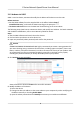
Table Of Contents
- Legal Information
- Chapter 1 Overview
- Chapter 2 Device Activation and Accessing
- Chapter 3 Face Capture
- Chapter 4 PTZ
- Chapter 5 Live View
- 5.1 Live View Parameters
- 5.1.1 Start and Stop Live View
- 5.1.2 Aspect Ratio
- 5.1.3 Live View Stream Type
- 5.1.4 Quick Set Live View
- 5.1.5 Select the Third-Party Plug-in
- 5.1.6 Start Digital Zoom
- 5.1.7 Conduct Regional Focus
- 5.1.8 Conduct Regional Exposure
- 5.1.9 Count Pixel
- 5.1.10 Light
- 5.1.11 Operate Wiper
- 5.1.12 Lens Initialization
- 5.1.13 Track Manually
- 5.1.14 Conduct 3D Positioning
- 5.1.15 OSD Menu
- 5.1.16 Display Target Information on Live View
- 5.2 Set Transmission Parameters
- 5.3 Smart Display
- 5.1 Live View Parameters
- Chapter 6 Video and Audio
- Chapter 7 Video Recording and Picture Capture
- Chapter 8 Event and Alarm
- Chapter 9 Arming Schedule and Alarm Linkage
- Chapter 10 Network Settings
- Chapter 11 System and Security
- 11.1 View Device Information
- 11.2 Restore and Default
- 11.3 Search and Manage Log
- 11.4 Import and Export Configuration File
- 11.5 Export Diagnose Information
- 11.6 Reboot
- 11.7 Upgrade
- 11.8 View Open Source Software License
- 11.9 Set Live View Connection
- 11.10 Time and Date
- 11.11 Set RS-485
- 11.12 Security
- Appendix A. Device Command
- Appendix B. Device Communication Matrix

4. Input
Mounng Height of the device.
5. Input or draw the min. pupil distance and the max. pupil distance.
The Min. Pupil Distance and the Max. Pupil Distance are used to improve detecon accuracy.
Only targets whose pupil distance are between the maximum distance and the minimum
distance trigger the capture.
Click
and to draw the distance on live image, or input values in the text elds of Min. Pupil
Distance and Max. Pupil Distance.
6. Click Save.
7. Set arming schedule. See Set Arming Schedule .
8. Set linkage method. See Linkage Method
Sengs .
3.1.2 Expert Mode
Sengs
Steps
1.
Oponal: Click Lock to lock PTZ control to prevent the interrupon from other PTZ related
acon during conguraon.
Normally, the PTZ control is automacally locked when you enter the conguraon interface.
You can manually resume the lock when the countdown is over.
2. Input Mounng Height of the device.
3. Set
detecon scenes and detecon areas.
1) Select a detecon scene.
2) Adjust the live image to a desired scene. You can use PTZ control
buons or click to locate
a scene with a face.
3) Click
, and draw a detecon area on live image.
4) Input or draw the min. pupil distance and the max. pupil distance.
The Min. Pupil Distance and the Max. Pupil Distance are used to improve
detecon
accuracy. Only targets whose pupil distance are between the maximum distance and the
minimum distance trigger the capture.
Click
and to draw the distance on live image, or input values in the text elds of Min.
Pupil Distance and Max. Pupil Distance.
5) Click Save.
6) Repeat above steps to set other
detecon scenes and areas.
4. Set patrol schedule.
1) Click Patrol Schedule.
2) Draw
me bars as desired.
3) Click a me bar and click Conguraon.
4) Edit patrol path and input dwell me for each detecon scene.
Add a
detecon scene to the patrol path.
Adjust the order of the scenes.
Delete the detecon scene.
E Series Network Speed Dome User Manual
8