TURBO HD D8T Series Bullet & Turret Camera User Manual UD05333B-A User Manual Thank you for purchasing our product. If there are any questions, or requests, do not hesitate to contact the dealer. This manual applies to the models below: Type Model Type I Camera DS-2CE16D8T-(A)IT3Z(E) Type II Camera DS-2CE56D8T-IT3Z(E) This manual may contain technical incorrect places or printing errors, and the content is subject to change without notice. The updates will be added to the new version of this manual.
Regulatory Information FCC Information Please take attention that changes or modification not expressly approved by the party responsible for compliance could void the user’s authority to operate the equipment. FCC compliance: This equipment has been tested and found to comply with the limits for a Class A digital device, pursuant to part 15 of the FCC Rules. These limits are designed to provide reasonable protection against harmful interference when the equipment is operated in a commercial environment.
Safety Instruction These instructions are intended to ensure that user can use the product correctly to avoid danger or property loss. The precaution measure is divided into “Warnings” and “Cautions”. Warnings: Serious injury or death may occur if any of the warnings are neglected. Cautions: Injury or equipment damage may occur if any of the cautions are neglected. Warnings Follow these safeguards to prevent serious injury or death.
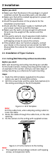
1 Introduction 1.1 Product Features The camera is applicable for both indoor and outdoor conditions, and the application scenarios include road, warehouse, underground parking lot, bar, etc.. The main features are as follows: High performance CMOS sensor Low illumination, 0.005 Lux @ (F1.8, AGC ON), 0 Lux with IR IR cut filter with auto switch OSD menu with configurable parameters Auto white balance Internal synchronization SMART IR mode PoC (with -E) 3-axis adjustment 1.
2 Installation Before you start: Make sure that the device in the package is in good condition and all the assembly parts are included. Make sure that all the related equipment is power-off during the installation. Check the specification of the products for the installation environment. Check whether the power supply is matched with your power output to avoid the damage. Make sure the wall is strong enough to withstand three times the weight of the camera and the bracket.
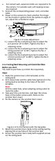
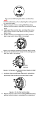
For cement wall, expansion bolts are required to fix the camera. For wooden wall, self-tapping screws are required. 5. Connect the corresponding power cord, and video cable. 6. Power on the camera to check whether the image on the monitor is gotten from the optimum angle. If not, adjust the surveillance angle. 0° to 360° 1 2 0° to 90° 3 0° to 360° Figure 2-3 3-axis Adjustment 1) Loosen the No.1 adjusting screw to adjust the pan position [0° to 360°]. Tighten the No.1 adjusting screw.
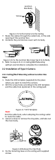
Junction Box Body Screw Figure 2-5 Fix the Camera to the Ceiling 7. Route the cables through the cable hole, or the side opening of the junction box. 8. Combine the junction box cover with its body. Figure 2-6 Fix the Junction Box Cover back to its Body 9. Refer to step 6 of 2.1.1 Ceiling/Wall Mounting without Junction Box to complete the installation. 2.2 Installation of Type II Camera 2.2.1 Ceiling/Wall Mounting without Junction Box Steps: 1.
Figure 2-9 Fix the Mounting Base on the Ceiling Note: The supplied screw package contains self-tapping screws, and expansion bolts. For cement wall, expansion bolts are required to fix the camera. For wooden wall, self-tapping screws are required. 5. Route the cables through the cable hole, or the side opening. 6. Install the main body to the mounting base and insert the clip plate. Figure 2-10 Install the Turret Camera 7. Tighten the screws with the screw driver. 8.
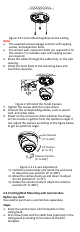
Figure 2-12 Drill Template of the Junction Box Note: Drill the cable hole, when adopting the ceiling outlet to route the cable. 3. Refer to step 3 of 2.2.1 Ceiling/Wall Mounting without Junction Box to take out the camera’s main body. 4. Take apart the junction box, and align the screw holes of the camera with those on the junction box’s cover. 5. Fix the camera’s mounting base on the junction box’s cover with three PM4 × 10 screws. Figure 2-13 Secure Screws on Junction Box’s Cover 6.
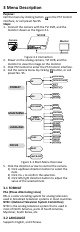
3 Menu Description Purpose: Call the menu by clicking button on the PTZ Control interface, or call preset No.95. Steps: 1. Connect the camera with the TVI DVR, and the monitor shown as the Figure 3-1. TVI DVR Camera Monitor Figure 3-1 Connection 2. Power on the analog camera, TVI DVR, and the monitor to view the image on the monitor. 3. Click PTZ Control to enter the PTZ Control interface. 4. Call the camera menu by clicking button, or call preset No. 95.
3.3 FOCUS Move the cursor to FOCUS, and press the Iris+ to enter the submenu. Click FOCUS+, FOCUS-, ZOOM+, and ZOOM- to adjust the focus. 3.4 MAIN MENU 3.4.1 AE (AUTO EXPOSURE) Auto Exposure describes the brightness-related parameters, which can be adjusted by BRIGHTNESS, EXPOSURE MODE, AGC, and SENSE UP. EXPOSURE BRIGHTNESS EXPOSURE MODE AGC SENSE UP RETURN 5 GLOBAL MIDDLE 0 Figure 3-3 AE BRIGHTNESS Brightness refers to the brightness of the image.
the environment. It can remove unrealistic color casts in the image. You can set WB mode as ATW, or MWB. ATW (Aoto Tracking White Balance) Under ATW mode, white balance is being adjusted automatically according to the color temperature of the scene illumination. MWB (Manual White Balance) You can set the R GAIN/B GAIN value from 1 to 255 to adjust the shades of red/blue color of the image. WB MODE R GAIN B GAIN MWB 5 5 RETURN Figure 3-4 MWB MODE 3.4.
CONTRAST This feature enhances the difference in color and light between parts of an image. You can set the CONTRAST value from 1 to 10. SHARPNESS Sharpness determines the amount of detail an imaging system can reproduce. You can set the SHARPNESS value from 1 to 10. COLOR GAIN Adjust this feature to change the saturation of the color. The value ranges from 1 to 10.
position and size of the area. Set the SENSITIVITY from 0 to 100. CAMERA ID Edit the camera ID on this section. CAM ID SETTING MODE CAM ID X POSITION Y POSITION RETURN ON 75 36 16 Figure 3-9 CAM ID SETTING Set the MODE as on. Click up/don left/right button to choose the camera ID and the position. 3.4.6 RESET Reset all the settings to the default. 3.4.7 SAVE & EXIT Move the cursor to SAVE & EXIT and click Iris+ to save the setting and exit the menu.