olorVu 5 MP Bullet and Turret Cameras User Manual 122919NA DS-2CE10HFT-F • DS-2CE10HFT-F28 DS-2CE12HFT-F • DS-2CE12HFT-F28 DS-2CE72HFT-F • DS-2CE72HFT-F28
Contents User Manual ........................................................... 3 Regulatory Information ..................................................... 3 FCC Information ........................................................... 3 FCC Compliance ........................................................... 3 FCC Conditions ........................................................... 3 EU Conformity Statement .................................................. 3 Industry Canada ICES-003 Compliance .....
User Manual Thank you for purchasing our product. If there are any questions or requests, please contact your dealer. This manual applies to the models below: Type Type I Camera Type II Camera Type III Camera Model DS-2CE10HFT-F DS-2CE10HFT-F28 DS-2CE12HFT-F DS-2CE12HFT-F28 DS-2CE72HFT-F DS-2CE72HFT-F28 This manual may contain technical mistakes or printing errors, and the content is subject to change without notice. Updates will be added to new versions of this manual.
Voltage Directive 2014/35/EU, the EMC Directive 2014/30/EU, the RoHS Directive 2011/65/EU. 2012/19/EU (WEEE Directive): Products marked with this symbol cannot be disposed of as unsorted municipal waste in the European Union. For proper recycling, return this product to your local supplier upon the purchase of equivalent new equipment, or dispose of it at designated collection points. For more information see: www.recyclethis.info.
Input voltage should meet both the SELV (Safety Extra Low Voltage) and the Limited Power Source with 12 VDC according to the IEC60950-1 standard. Refer to technical specifications for detailed information. Do not connect multiple devices to one power adapter to avoid overheating or a fire hazard caused by overload. Make sure that the plug is firmly connected to the power socket. Make sure that the device is firmly fixed if wall mounting or ceiling mounting is used.
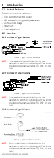
1 Introduction 1.1 Product Features The main features are as follows: • • • • • High performance CMOS sensor OSD menu with configurable parameters 24-hour color image Smart light 3-axis adjustment 1.2 Overview 1.2.1 Overview of Type I Camera Figure 1, Type 1 Camera Overview NOTE: Press and hold the switch button for five seconds to switch the video output. Four kinds of video outputs are available: TVI, AHD, CVI, and CVBS. 1.2.
2 Installation Before You Start • • • • • • • Make sure that the device in the package is in good condition and all assembly parts are included. Make sure that all related equipment is powered off during the installation. Check the products’ specifications for the installation environment. Check whether the power supply matches your power output to avoid damage. Make sure the wall is strong enough to withstand three times the weight of the camera and the mount.
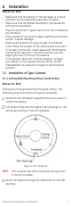
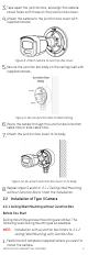
Figure 5, Secure the Camera to the Ceiling Attach the bracket to the ceiling, and secure the camera with supplied screws. NOTES: The supplied screw package contains selftapping screws and expansion bolts. For a concrete wall/ceiling, expansion bolts are required to fix the camera. For a wood wall/ceiling, self-tapping screws are required. Connect the power cord and video cable. Power on the camera to check if the image on the monitor is at an optimum angle.
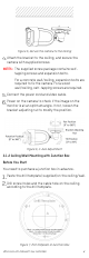
Take apart the junction box, and align the camera screw holes with those on the junction box cover. Attach the camera to the junction box cover with supplied screws. Figure 8, Attach Camera to Junction Box Cover Secure the junction box body on the ceiling/wall with supplied screws. Figure 9, Secure Junction Box on Wall/Ceiling Route the cables through the junction box’s bottom cable hole or side cable hole. Attach the junction box cover to its body.
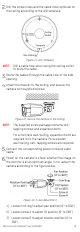
Drill the screw holes and the cable hole (optional) on the ceiling according to the drill template. Figure 11, Drill Template NOTE: Drill a cable hole when using the ceiling outlet to route the cable. Route the cables through the cable hole or the side opening. Attach the bracket to the ceiling, and secure the camera with supplied screws. Figure 12, Secure the Camera to the Ceiling NOTE: The supplied screw package contains selftapping screws and expansion bolts.
2.3 Installation of Type III Camera 2.3.1 Ceiling/Wall Mounting without Junction Box Before You Start Ceiling mounting and wall mounting are similar. The following uses ceiling mounting as an example. Disassemble the camera by rotating it to align the notch to one of the lines, as shown below. Figure 14, Dissemble the Camera Pry the mounting base open with a flat object (for example, a coin). Figure 15, Pry the Mounting Base Paste the drill template (supplied) to where you want to install the camera.
NOTE: The supplied screw package contains selftapping screws and expansion bolts. Route the cables through the cable hole or side opening. Re-install and secure camera to the mounting base. Figure 18, Install the Camera Back Connect the corresponding cables such as power cord and video cable. Power on the camera to check if the image on the monitor is at an optimum angle. If not, adjust the camera according to the figure below to get an optimum angle.
Figure 20, Drill Template NOTE: Drill a cable hole when using a ceiling outlet to route the cable. Take apart the junction box, and align the mounting base screw holes with those on the junction box cover. Install the mounting base to the junction box cover with three PM4 screws. Figure 21, Secure Junction Box Cover Screws Secure the junction box’s body on the wall with four PA4 × 25 screws. Figure 22, Secure Junction Box Body Route the cables through the junction box’s bottom or side cable hole.
Figure 23, Finish the Installation 3 Menu Description Follow the steps below to call the menu. NOTE: The actual display may vary by camera model. Connect the camera to the TVI DVR and the monitor, as shown below. Figure 24, Connection Power on the camera, TVI DVR, and the monitor to view the image on the monitor. Click PTZ Control to enter the PTZ Control interface. Call the camera menu by clicking the preset No. 95.
Figure 25, Main Menu Overview Click the direction arrow to control the camera. 1) Click up/down button to select the item. 2) Click Iris + to confirm the selection. 3) Click left/right button to adjust selected value.
3.1 VIDEO FORMAT You can set the video format to 5 MP @ 20 fps, 4 MP @ 30 fps, 4 MP @ 25 fps, 2 MP @ 30 fps, or 2 MP @ 25 fps. 3.2 EXPOSURE 3.2.1 EXPOSURE MODE You can set the EXPOSURE MODE to GLOBAL, BLC, HLC, WDR, or HLS. • GLOBAL GLOBAL refers to the normal exposure mode, which adjusts lighting distribution, variations, and nonstandard processing.
3.3 VIDEO SETTINGS Move the cursor to VIDEO SETTINGS and click Iris+ to enter the submenu. IMAGE MODE, WHITE BALANCE, BRIGHTNESS, CONTRAST, SHARPNESS, SATURATION, 3DNR, and MIRROR are adjustable. Figure 26, Video Settings 3.3.1 IMAGE MODE IMAGE MODE adjusts the image saturation. You can set it to STD (Standard) or HIGH-SAT (High Saturation). 3.3.2 WHITE BALANCE White balance, the camera’s white rendition function, adjusts the color temperature according to the environment.
3.3.6 SATURATION Saturation is the proportion of pure chromatic color in the total color sensation. Adjust this feature to change the color intensity. 3.3.7 3 DNR (3D DNR) 3 DNR refers to 3D digital noise reduction. Compared to general 2D digital noise reduction, 3D digital noise reduction processes the noise between two frames in addition to processing the noise in one frame. The noise will be much less and the video will be clearer. 3.3.8 MIRROR OFF, H, V, and HV are selectable for mirror.
3.7 EXIT Move the cursor to EXIT and click Iris+ to exit the menu. 3.8 SAVE & EXIT Move the cursor to SAVE & EXIT and click Iris+ to save the settings and exit the menu.