2 MP PIR Siren Full Time Color Camera User Manual User Manual Thank you for purchasing our product. If there are any questions, or requests, do not hesitate to contact the dealer. This manual applies to the models below: Type Model Type I Camera DS-2CE12DFT-PIRXOF Type II Camera DS-2CE72DFT-PIRXOF This manual may contain several technical mistakes or printing errors, and the content is subject to change without notice. The updates will be added to the new version of this manual.
Regulatory Information FCC Information Please take attention that changes or modification not expressly approved by the party responsible for compliance could void the user’s authority to operate the equipment. FCC compliance: This equipment has been tested and found to comply with the limits for a Class A digital device, pursuant to part 15 of the FCC Rules. These limits are designed to provide reasonable protection against harmful interference when the equipment is operated in a commercial environment.
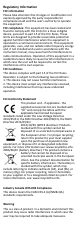
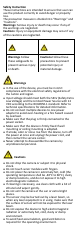
Safety Instruction These instructions are intended to ensure that user can use the product correctly to avoid danger or property loss. The precaution measure is divided into “Warnings” and “Cautions”. Warnings: Serious injury or death may occur if any of the warnings are neglected. Cautions: Injury or equipment damage may occur if any of the cautions are neglected. Warnings Follow these safeguards to prevent serious injury or death.
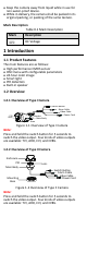
Keep the camera away from liquid while in use for non-water-proof device. While in delivery, the camera shall be packed in its original packing, or packing of the same texture. Mark Description Table 0-1 Mark Description Mark Description DC Voltage 1 Introduction 1.1 Product Features The main features are as follows: High performance CMOS sensor OSD menu with configurable parameters 24-hour color image Smart light PIR detection Built-in speaker 1.2 Overview 1.2.
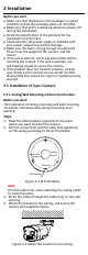
2 Installation Before you start Make sure that the device in the package is in good condition and all the assembly parts are included. Make sure that all the related equipment is power-off during the installation. Check the specification of the products for the installation environment. Check whether the power supply is matched with your power output to avoid the damage. Make sure the wall is strong enough to withstand three times the weight of the camera, and the mount.
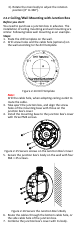
Note: The supplied screw package contains self-tapping screws, and expansion bolts. For cement wall/ceiling, expansion bolts are required to fix the camera. For wooden wall/ceiling, self-tapping screws are required. 5. Connect the corresponding power cord, and video cable. 6. Power on the camera to check whether the image on the monitor is gotten from the optimum angle. If not, loosen the trim ring to adjust the position.
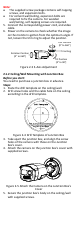
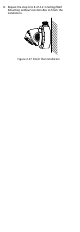
Junction Box Body Figure 2-6 Secure the Junction Box on the Wall/Ceiling 6. Route the cables through the bottom cable hole, or the side cable hole of the junction box. 7. Combine the junction box cover with its body. Figure 2-7 Combine the Junction Box Cover back to its Body 8. Repeat the step 5 to 6 of 2.1.1 Ceiling/Wall Mounting without Junction Box to finish the installation. 2.2 Installation of Type II Camera 2.2.
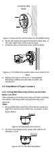
3. Paste the drill template (supplied) to the place where you want to install the camera. Figure 2-10 Drill Template Note: Drill the cable hole, when adopting the ceiling outlet to route the cable. 4. Attach the mounting base to the ceiling and secure it with supplied screws. For cement ceiling, you need to install the expansion bolts at first.
3). Rotate the main body to adjust the rotation position [0° to 360°]. 2.2.2 Ceiling/Wall Mounting with Junction Box Before you start: You need to purchase a junction box in advance. The installation of ceiling mounting and wall mounting are similar. Following takes wall mounting as an example. Steps: 1. Paste the drill template on the wall. 2. Drill screw holes and the cable hole (optional) on the wall according to the drill template.
8. Repeat the step 6 to 8 of 2.2.1 Ceiling/Wall Mounting without Junction Box to finish the installation.
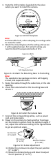
3 Menu Description Please follow the steps below to call the menu. NOTE: The actual display may vary with your camera model. Steps: 1. Connect the camera with the TVI DVR, and the monitor, shown as the figure 3-1. TVI DVR Camera Monitor Figure 3-1 Connection 2. Power on the camera, TVI DVR, and the monitor to view the image on the monitor. 3. Click PTZ Control to enter the PTZ Control interface. 4. Call the camera menu by clicking button, or call the preset No. 95.
1). Click up/down direction button to select the item. 2). Click Iris + to confirm the selection. 3). Click left/right direction button to adjust the value of the selected item. 3.1 VIDEO FORMAT You can set the video format to 2MP@25fps or 2MP@30fps. 3.2 EXPOSURE EXPOSURE MODE You can set the EXPOSURE MODE to GLOBAL, BLC, HLC, WDR, or HLS. GLOBAL GLOBAL refers to the normal exposure mode which adjusts lighting distribution, variations, and non-standard processing.
VIDEO SETTINGS IMAGE MODE WHITE BALANCE BRIGHTNESS CONTRAST SHARPNESS SATURATION 3DNR MIRROR BACK EXIT SAVE & EXIT STD 5 5 5 5 5 OFF Figure 3-3 VIDEO SETTING IMAGE MODE IMAGE MODE is used to adjust the image saturation, and you can set it to STD (Standard) or HIGH-SAT (High Saturation). WHITE BALANCE White balance, the white rendition function of the camera, is to adjust the color temperature according to the environment. It can remove unrealistic color casts in the image.
between two frames besides processing the noise in one frame. The noise will be much less and the video will be clearer. MIRROR OFF, H, V, and HV are selectable for mirror. OFF: The mirror function is disabled. H: The image flips 180° horizontally. V: The image flips 180° vertically. HV: The image flips 180° both horizontally and vertically. 3.4 SMART LIGHT Under the SMART LIGHT sub-menu, you can set the mode to OFF or AUTO. OFF Set it to OFF to give up this function.
3.5.7 DPC DPC refers to defective pixel correction. Defective pixels are pixels on a display that are not performing as expected. This function is used to correct pixels like that. 3.6 FACTORY DEFAULT Reset all the settings to the factory default. 3.7 EXIT Move the cursor to EXIT and click Iris+ to exit the menu. 3.8 SAVE & EXIT Move the cursor to SAVE & EXIT and click Iris+ to save the settings, and exit the menu.