TURBO HD H8T Series Dome Camera User Manual User Manual Thank you for purchasing our product. If there are any questions, or requests, do not hesitate to contact the dealer. This manual applies to the models below: Type Model Type I Camera DS-2CE59H8T-(A)VPIT3ZF Type II Camera DS-2CE56H8T-(A)ITZF Type III Camera DS-2CE5AH8T-(A)VPIT3ZF This manual may contain technical incorrect places or printing errors, and the content is subject to change without notice.
Regulatory Information FCC Information Please take attention that changes or modification not expressly approved by the party responsible for compliance could void the user’s authority to operate the equipment. FCC compliance: This equipment has been tested and found to comply with the limits for a Class A digital device, pursuant to part 15 of the FCC Rules. These limits are designed to provide reasonable protection against harmful interference when the equipment is operated in a commercial environment.
Safety Instruction These instructions are intended to ensure that user can use the product correctly to avoid danger or property loss. The precaution measure is divided into “Warnings” and “Cautions”. Warnings: Serious injury or death may occur if any of the warnings are neglected. Cautions: Injury or equipment damage may occur if any of the cautions are neglected. Warnings Follow these safeguards to prevent serious injury or death.
To avoid heat accumulation, good ventilation is required for the operating environment. Keep the camera away from liquid while in use for nonwater-proof device. While in delivery, the camera shall be packed in its original packing, or packing of the same texture. Mark Description Table 0-1 Mark Description Mark Description DC Voltage AC Voltage 1 Introduction 1.
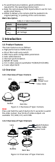
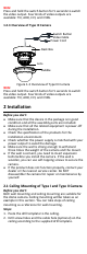
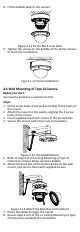
Note: Press and hold the switch button for 5 seconds to switch the video output. Four kinds of video outputs are available: TVI, AHD, CVI, and CVBS. 1.2.3 Overview of Type III Camera Switch Button Video Cable Power Cord Back Box Lens Bubble Figure 1-3 Overview of Type III Camera Note: Press and hold the switch button for 5 seconds to switch the video output. Four kinds of video outputs are available: TVI, AHD, CVI, and CVBS.
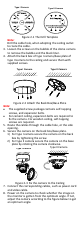
Type I Camera Type II Camera Figure 2-1 The Drill Template Note: Drill the cable hole, when adopting the ceiling outlet to route the cable. 3. Loosen the screws on the bubble of the dome camera to remove the bubble and the black liner. 4. Attach the back box of type I camera/base plate of type II camera to the ceiling and secure them with supplied screws.
Type I Camera Type II Camera 0° to 355° 0° to 340° 0° to 75° 0° to 75° 0° to 355° 0° to 355° Figure 2-4 3-Axis Adjustment 9. Fit the black liner back to the camera and tighten the screws on the bubble of the dome camera to finish the installation. 2.2 Wall Mounting of Type I and Type II Camera Before you start: You need to purchase a wall mount first. Steps: 1. Drill 4 screw holes in the wall according to the holes of the mount. 2.
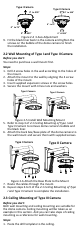
2. Drill screw holes and the cable hole (optional) on the ceiling according to the supplied drill template. Figure 2-7 The Drill Template Note: Drill the cable hole (hole A) when adopting the ceiling outlet to route the cable. 3. Loosen the screws on the bubble of the dome camera to remove the bubble. Figure 2-8 Remove the Bubble and the Black Liner 4. Attach the back box of camera to the ceiling and secure them with supplied screws.
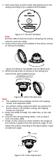
8. Fit the bubble back to the camera. Figure 2-11 Fit the Black Liner Back 9. Tighten the screws on the bubble of the dome camera to finish the installation. Figure 2-12 Finish Installation 2.4 Wall Mounting of Type III Camera Before you start: You need to purchase a wall mount first. Steps: 1. Drill 4 screw holes in the wall according to the holes of the mount. 2. Attach the mount to the wall by aligning the 4 screw holes of the mount. 3. Insert supplied expansion screws in the screw holes. 4.
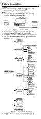
3 Menu Description Purpose: Call the menu by clicking the button on the PTZ Control interface, or call preset No.95. Steps: 1. Connect the camera with the TVI DVR, and the monitor, shown as the figure 3-1. TVI DVR Camera Monitor Figure 3-1 Connection 2. Power on the analog camera, TVI DVR, and the monitor to view the image on the monitor. 3. Click PTZ Control to enter the PTZ Control interface. 4. Call the camera menu by clicking button, or call preset No. 95.
1). Click up/down direction button to select the item. 2). Click Iris + to confirm the selection. 3). Click left/right direction button to adjust the value of the selected item. 3.1 VIDOE FORMAT You can set the video format as 5MP@20fps, 4MP@25fps, 4MP@30fps, 2MP@25fps, and 2MP@30fps. Note: When switching the video output as CVBS, you can set the video format as PAL, or NTSC.
You can turn on/off the IR LIGHT and set the value of SMART IR in this menu DAY/NIGHT MODE IR LIGHT SMART IR BACK EXIT SAVE & EXIT B&W ON 2 Figure 3-4 B & W IR LIGHT You can turn on/off the IR LIGHT to meet the requirements of different circumstances. SMART IR The Smart IR function is used to adjust the light to its most suitable intensity, and prevent the image from over exposure. The SMART IR value can be adjusted from 0 to 3. The higher the value is, the more obvious effects are.
VIDEO SET TINGS IMAGE MODE WHITE BALANCE BRIGHTNESS CONTRAST SHARPNESS SATURATION 3DNR MIRROR BACK EXIT SAVE & EXIT STD 5 5 5 5 5 OFF Figure 3-6 VIDEO SETTINGS IMAGE MODE IMAGE MODE is used to adjust the image saturation, and you can set it as STD (Standard), or HIGH-SAT (High Saturation). WHITE BALANCE White balance, the white rendition function of the camera, is to adjust the color temperature according to the environment. It can remove unrealistic color casts in the image.
MIRROR OFF, H, V, and HV are selectable for mirror. OFF: The mirror function is disabled. H: The image flips 180° horizontally. V: The image flips 180° vertically. HV: The image flips 180° both horizontally and vertically. 3.5 FUNCTIONS In the FUNCTIONS submenu, you can set the privacy mask, and the motion detection of the camera. MOTION DETECTION In the user-defined motion detection surveillance area, the moving object can be detected and the alarm will be triggered.