TURBO HD U1T Series Turret & Dome Camera User Manual User Manual Thank you for purchasing our product. If there are any questions, or requests, do not hesitate to contact the dealer.
Regulatory Information FCC Information Please take attention that changes or modification not expressly approved by the party responsible for compliance could void the user’s authority to operate the equipment. FCC compliance: This equipment has been tested and found to comply with the limits for a Class A digital device, pursuant to part 15 of the FCC Rules. These limits are designed to provide reasonable protection against harmful interference when the equipment is operated in a commercial environment.
Safety Instruction These instructions are intended to ensure that user can use the product correctly to avoid danger or property loss. The precaution measure is divided into “Warnings” and “Cautions”. Warnings: Serious injury or death may occur if any of the warnings are neglected. Cautions: Injury or equipment damage may occur if any of the cautions are neglected. Warnings Follow these safeguards to prevent serious injury or death.
While in delivery, the camera shall be packed in its original packing, or packing of the same texture. Mark Description Table 0-1 Mark Description Mark Description DC Voltage 1 Introduction 1.1 Product Features The main features are as follows: High performance CMOS sensor IR cut filter with auto switch OSD menu with configurable parameters Auto white balance Internal synchronization SMART IR mode 3-axis adjustment 1.
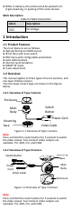
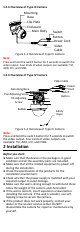
1.2.3 Overview of Type III Camera Mounting Base Clip Plate Enclosure Main Body IN DC 12 V Switch Button Power Cord Video Cable Figure 1-3 Overview of Type III Camera Note: Press and hold the switch button for 5 seconds to switch the video output. Four kinds of video outputs are available: TVI, AHD, CVI, and CVBS. 1.2.
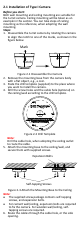
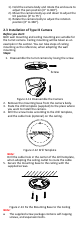
2.1 Installation of Type I Camera Before you start: Both wall mounting and ceiling mounting are suitable for the turret camera. Ceiling mounting will be taken as an example in this section. You can take steps of ceiling mounting as the reference, when adopting the wall mounting. Steps: 1. Disassemble the turret camera by rotating the camera to align the notch to one of the marks, as shown in the figure below. Mark Notch Figure 2-1 Disassemble the Camera 2.
. Align the camera with the mounting base, and tighten the screws to secure the camera on the mounting base. Figure 2-4 Secure the Camera with Mounting Base 8. Connect the corresponding cables, such as power cord, and video cable. 9. Power on the camera to check whether the image on the monitor is gotten from the optimum angle. If not, adjust the camera according to the figure below to get an optimum angle.
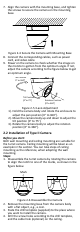
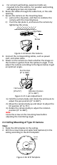
Figure 2-7 Drill Template Note: Drill the cable hole in the center of the drill template, when adopting the ceiling outlet to route the cable. 5. Secure the mounting base to the ceiling with the supplied screws. Expansion Bolts Self-tapping Screws Figure 2-8 Fix the Mounting Base to the Ceiling Note: The supplied screw package contains self-tapping screws, and expansion bolts. For cement wall/ceiling, expansion bolts are required to fix the camera.
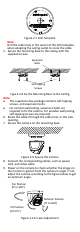
1). Hold the camera body and rotate the enclosure to adjust the pan position [0° to 360°]. 2). Move the camera body up and down to adjust the tilt position [0° to 75°]. 3). Rotate the camera body to adjust the rotation position [0° to 360°]. 2.3 Installation of Type III Camera Before you start: Both wall mounting and ceiling mounting are suitable for the turret camera. Ceiling mounting will be taken as an example in this section.
For cement wall/ceiling, expansion bolts are required to fix the camera. For wooden wall/ceiling, self-tapping screws are required. 6. Route the cables through the cable hole, or the side opening. 7. Secure the camera on the mounting base. 1) pull out the clip plate, and then to combine the camera with the mounting base. 2) Push the clip plate in, and secure the camera by tightening the screw. Clip Plate Screw Figure 2-14 Secure the Camera 8.
Note: Cable hole is required, when adopting the ceiling outlet to route cables. 3. Loosen the screws with a hex wrench (supplied) to remove the bubble. Figure 2-17 Remove the Bubble 4. Fix the mounting base on the ceiling with supplied screws. Figure 2-18 Fix the Mounting Base 5. Route the cables through the cable hole, or the side opening. 6. Connect the corresponding cables, such as power cord, and video cable. 7.
3 Menu Description Purpose: Call the menu by clicking the button on the PTZ Control interface, or call preset No.95. Steps: 1. Connect the camera with the TVI DVR, and the monitor, shown as the figure 3-1. TVI DVR Camera Monitor Figure 3-1 Connection 2. Power on the analog camera, TVI DVR, and the monitor to view the image on the monitor. 3. Click PTZ Control to enter the PTZ Control interface. 4. Call the camera menu by clicking button, or call preset No. 95.
3). Click left/right direction button to adjust the value of the selected item. 3.1 VIDEO FORMAT You can set the video format as 8MP@12.5 fps, 8 MP@15fps, 5MP@20fps, 4MP@25fps, 4MP@30fps, 2MP@25fps, and 2MP@30fps. Note: When switching the video output as CVBS, you can set the video format as PAL, or NTSC. When switching the video output as AHD, only 5MP@20fps is supported. When switching the video output as CVI, you can set the video format as 8MP@12.5 fps, or 8MP@15fps. 3.
B & W (Black and White) The image is black and white all the time, and the IR LIGHT turns on in the poor light conditions. You can turn on/off the IR LIGHT and set the value of SMART IR in this menu DAY/NIGHT MODE IR LIGHT SMART IR BACK EXIT SAVE & EXIT B&W ON 2 Figure 3-4 B & W IR LIGHT You can turn on/off the IR LIGHT to meet the requirements of different circumstances.
3.4 VIDEO SETTINGS Move the cursor to VIDEO SETTINGS and click Iris+ to enter the submenu. IMAGE MODE, WHITE BALANCE, BRIGHTNESS, CONTRAST, SHARPNESS, SARUTATION, DNR, and MIRROR are adjustable. VIDEO SETTINGS IMAGE MODE WHITE BALANCE BRIGHTNESS CONTRAST SHARPNESS SATURATION DNR MIRROR BACK EXIT SAVE & EXIT STD 5 5 5 5 5 OFF Figure 3-6 VIDEO SETTINGS IMAGE MODE IMAGE MODE is used to adjust the image saturation, and you can set it as STD (Standard), or HIGH-SAT (High Saturation).
SHARPNESS Sharpness determines the amount of detail an imaging system can reproduce. You can set the SHARPNESS value from 1 to 9. SATURATION Adjust this feature to change the saturation of the color. The value ranges from 1 to 9. DNR (Digital Noise Reduction) The DNR function can decrease the noise effect, especially when capturing moving images in poor light conditions and delivering more accurate and sharp image. You can set the DNR value from 1 to 9. MIRROR OFF, H, V, and HV are selectable for mirror.