H0T Series Bullet & Dome Camera User Manual User Manual Thank you for purchasing our product. If there are any questions, or requests, do not hesitate to contact the dealer.
Regulatory Information FCC Information Please take attention that changes or modification not expressly approved by the party responsible for compliance could void the user’s authority to operate the equipment. FCC compliance: This equipment has been tested and found to comply with the limits for a Class A digital device, pursuant to part 15 of the FCC Rules. These limits are designed to provide reasonable protection against harmful interference when the equipment is operated in a commercial environment.
Safety Instruction These instructions are intended to ensure that user can use the product correctly to avoid danger or property loss. The precaution measure is divided into “Warnings” and “Cautions”. Warnings: Serious injury or death may occur if any of the warnings are neglected. Cautions: Injury or equipment damage may occur if any of the cautions are neglected. Warnings Follow these safeguards to prevent serious injury or death.
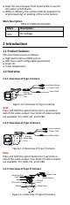
Keep the camera away from liquid while in use for non-water-proof device. While in delivery, the camera shall be packed in its original packing, or packing of the same texture. Mark Description Table 0-1 Mark Description Mark Description DC Voltage 1 Introduction 1.1 Product Features The main features are as follows: High performance CMOS sensor OSD menu with configurable parameters Smart IR 3-Axis Adjustment 1.2 Overview 1.2.
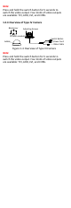
Note: Press and hold the switch button for 5 seconds to switch the video output. Four kinds of video outputs are available: TVI, AHD, CVI, and CVBS. 1.2.4 Overview of Type IV Camera Black Liner Adjusting Screws IR Zoom module Bubble Switch Button Power Cord Video Cable Figure 1-4 Overview of Type III Camera Note: Press and hold the switch button for 5 seconds to switch the video output. Four kinds of video outputs are available: TVI, AHD, CVI, and CVBS.
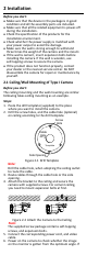
2 Installation Before you start: Make sure that the device in the package is in good condition and all the assembly parts are included. Make sure that all the related equipment is power-off during the installation. Check the specification of the products for the installation environment. Check whether the power supply is matched with your power output to avoid the damage. Make sure the wall is strong enough to withstand three times the weight of the camera and the mount.
not, adjust the camera according to the figure below. Pan Position [0° to 360°] Rotation Position [0° to 360°] Bracket Adjusting Screw Tilt Position [0° to 90°] Figure 2-3 3-Axis Adjustment 2.2 Ceiling/Wall Mounting of Type II Camera Before you start: The ceiling mounting and the wall mounting are similar. Following takes ceiling mounting as an example. Steps: 1. Paste the drill template (supplied) to the place where you want to install the camera. 2.
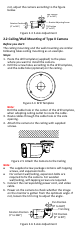
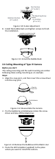
2.3 Ceiling Mounting of Type III Camera Before you start: The ceiling mounting and the wall mounting are similar. Following takes ceiling mounting as an example. Steps: 1. Paste the drill template (supplied) to the place where you want to install the camera. 2. Drill the screw holes and cable hole (optional) on the ceiling according to the drill template.
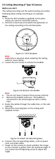
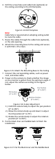
Pan Position [0° to 355°] Tilt Adjusting Screw Rotation Position [0° to 355°] Tilt Position [0° to 75°] Figure 2-10 3-Axis Adjustment 8. Install the bubble back and tighten screws to finish the installation. Figure 2-11 Install the Bubble Back 2.4 Ceiling Mounting of Type IV Camera Before you start: The ceiling mounting and the wall mounting are similar. Following takes ceiling mounting as an example. Steps: 1. Align the snap joint, and then insert the screw driver into the snap joint.
4. Drill the screw holes and cable hole (optional) on the ceiling according to the drill template. Figure 2-14 Drill Template Note: Cable hole is required when adopting ceiling outlet to route the cable. 5. Route the cables through the cable hole (optional), or the side opening. 6. Attach the mounting base to the ceiling and secure it with PA4 × 25 screws. Figure 2-15 Attach the Mounting Base to the Ceiling 7. Connect the corresponding cables, such as power cord, and video cable. 8.
3 Menu Description Please follow the steps below to call the menu. Note: The actual display may vary with your camera model. Steps: 1. Connect the camera with the TVI DVR, and the monitor, shown as the figure 3-1. TVI DVR Camera Monitor Figure 3-1 Connection 2. Power on the analog camera, TVI DVR, and the monitor to view the image on the monitor. 3. Click PTZ Control to enter the PTZ Control interface. 4. Call the camera menu by clicking button, or call preset No. 95.
2). Click Iris + to confirm the selection. 3). Click left/right direction button to adjust the value of the selected item. 3.1 VIDOE FORMAT You can set the video format to 5MP@20fps, 4MP@30fps, 4MP@25fps, 2MP@30fps, or 2MP@25fps. 3.2 EXPOSURE Exposure describes the brightness-related parameters, which can be adjusted by EXPOSURE MODE, SHUTTER and AGC.
B&W (Black and White) The image is black and white all the time, and the IR LIGHT turns on in the poor light conditions. You can turn on/off the IR LIGHT and set the value of SMART IR in this menu DAY/NIGHT B&W ON 2 MODE IR LIGHT SMART IR BACK EXIT SAVE & EXIT Figure 3-4 B&W IR LIGHT You can turn on/off the IR LIGHT to meet the requirements of different circumstances.
set the value from 1 to 9. The larger the value, the more sensitive the camera. 3.4 VIDEO SETTINGS Move the cursor to VIDEO SETTINGS and click Iris+ to enter the submenu. IMAGE MODE, WHITE BALANCE, BRIGHTNESS, CONTRAST, SHARPNESS, SARUTATION, DNR, and MIRROR are adjustable. VIDEO SETTINGS IMAGE MODE WHITE BALANCE BRIGHTNESS CONTRAST SHARPNESS SATURATION DNR MIRROR BACK EXIT SAVE & EXIT STD 5 5 5 5 5 OFF Figure 3-6 VIDEO SETTINGS IMAGE MODE IMAGE MODE is used to adjust the image saturation.
SATURATION Saturation is the proportion of pure chromatic color in the total color sensation. The saturation of a color is determined by a combination of light intensity and how much it is distributed across the spectrum of different wavelengths. DNR (Digital Noise Reduction) The DNR function can decrease the noise effect, especially when capturing moving images in poor light conditions and delivering more accurate and sharp image. MIRROR OFF, H, V, and HV are selectable for mirror.