DS-2CE57H0T-VPITF Dome Camera User Manual
Contents 1 Regulatory Information ............................................. 3 1.1 FCC Information .................................................. 3 1.2 FCC Conditions.................................................... 3 1.3 EU Conformity Statement ................................... 3 1.4 Industry Canada ICES-003 Compliance ............. 4 1.5 Warning............................................................... 4 1.6 Safety Instruction............................................... 4 1.6.
Thank you for purchasing our product. If there are any questions or requests, do not hesitate to contact the dealer. This manual applies to the models below: Model DS-2CE57H0T-VPITF This manual may contain several technical mistakes or printing errors, and the content is subject to change without notice. Updates will be added to the new versions of this manual. We will readily improve or update the products or procedures described in the manual. 1 Regulatory Information 1.
2012/19/EU (WEEE Directive): Products marked with this symbol cannot be disposed of as unsorted municipal waste in the European Union. For proper recycling, return this product to your local supplier upon the purchase of equivalent new equipment, or dispose of it at designated collection points. For more information see: www.recyclethis.info. 2006/66/EC (Battery Directive): This product contains a battery that cannot be disposed of as unsorted municipal waste in the European Union.
• Input voltage should meet both the SELV (Safety Extra Low Voltage) and the Limited Power Source with 12 VDC according to the IEC60950-1 standard. Refer to technical specifications for detailed information. • Do not connect multiple devices to one power adapter to avoid overheating or a fire hazard caused by overload. • Make sure that the plug is firmly connected to the power socket. • Make sure that the device is firmly fixed if wall mounting or ceiling mounting is used.
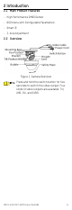
2 Introduction 2.1 Main Product Features • High Performance CMOS Sensor • OSD menu with Configurable Parameters • Smart IR • 3-Axis Adjustment 2.2 Overview Figure 1, Camera Overview Press and hold the switch button for five seconds to switch the video output. Four kinds of video outputs are available: TVI, AHD, CVI, and CVBS.
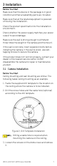
3 Installation Before You Start Make sure that the device in the package is in good condition and that all assembly parts are included. Make sure that all the related equipment is powered off during the installation. Check the product specification for the installation environment. Check whether the power supply matches your power output to avoid damage. Make sure the wall is strong enough to withstand three times the weight of the camera and the mount.
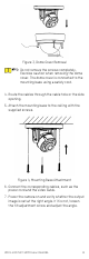
Figure 3, Dome Cover Removal Do not remove the screws completely. Exercise caution when removing the dome cover. The dome cover is connected to the mounting base using a safety cord. 4. Route the cables through the cable hole or the side opening. 5. Attach the mounting base to the ceiling with the supplied screws. Figure 4, Mounting Base Attachment 6. Connect the corresponding cables, such as the power cord and the video cable. 7.
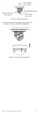
Figure 5, Angle Adjustment 8. Install the dome cover again and tighten the screws in order to complete installation.
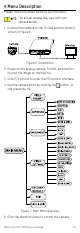
4 Menu Description Please follow the steps below to call the menu. The actual display may vary with your camera model. 1. Connect the camera to the TVI DVR and the monitor, shown in Figure 6. Figure 6, Connection 2. Power on the analog camera, TVI DVR, and monitor to view the image on the monitor. 3. Click PTZ Control to enter the PTZ Control interface. 4. Call the camera menu by clicking the call preset No. 95. button, or Figure 7, Main Menu Overview 5. Click the direction arrow to control the camera.
1) Click up/down direction button to select the item. 2) Click Iris+ to confirm the selection. 3) Click left/right direction button to adjust the value of the selected item. 4.1 Video Format You can set the video format to 5 MP @ 20 fps, 4 MP @ 30 fps, 4 MP @ 25 fps, 2 MP @ 30 fps, or 2 MP @ 25 fps. 4.2 Exposure Exposure describes the brightness-related parameters, which can be adjusted by EXPOSURE MODE, SHUTTER, and AGC.
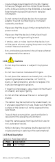
4.2.3 AGC (Automatic Gain Control) Optimizes the clarity of the image in poor light conditions. The AGC level can be set to HIGH, MEDIUM, or LOW. The noise will be amplified when setting the AGC level. 4.3 Day/Night Color, BW (Black and White), and Auto are selectable for the Day/Night switch. 4.3.1 Color The image is in color in day mode all the time. 4.3.2 B&W (Black and White) The image is black and white all the time, and the IR Light turns on in poor light conditions.
DAY/NIGHT MODE IR LIGHT SMART IR D N THRESHOLD N D THRESHOLD BACK EXIT SAVE & EXIT AUTO ON 2 5 5 Figure 10, Auto • IR Light: You can turn the IR Light on/off to meet the requirements of different circumstances. • Smart IR: Adjusts the light to its most suitable intensity and prevents the image from overexposure. The Smart IR value can be adjusted from 1 to 3. The higher the value, the more obvious the effect.
4.4.1 Image Mode Image Mode is used to adjust the image saturation. You can set it to STD (Standard), or High-Sat (High Saturation). 4.4.2 White Balance White balance, the white rendition function of the camera, is to adjust the color temperature according to the environment. It can remove unrealistic color casts in the image. You can set the mode to Auto or Manual. • Auto: White balance is adjusted automatically according to the color temperature of the scene illumination.
The DNR function can decrease the noise effect, especially when capturing moving images in poor light conditions and delivering more accurate and sharper images. 4.4.8 Mirror OFF, H, V, and HV are selectable for mirror. • OFF: The mirror function is disabled. • H: The image is flipped 180° horizontally. • V: The image is flipped 180° vertically. • HV: The image is flipped 180° both horizontally and vertically. 4.