
User Manual


UM DS-2CE5xH0T-Axxxxx 042318NA 9
Figure 11 Remove the Bubble and the Black Liner
4. Attach the back box of the camera to the ceiling
and secure with supplied screws.
Figure 12 Attach the Back Box
Note:
The supplied screw package contains self-tapping
screws and expansion bolts.
For a cement ceiling, expansion bolts are required to
fix the camera. For a wooden ceiling, self-tapping
screws are required.
5. Route the cables through the cable hole or the
side opening.
6. Connect the corresponding cables such as power
cord and video cable.
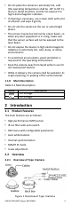
7. Power on the camera to check whether the
image on the monitor is at an optimum angle. If
not, adjust the camera according to the figure
below to get an optimum angle.
Figure 13 3-Axis Adjustment
8. Fit the bubble back onto the camera.