TURBO HD D8T Series Dome Camera User Manual UD05334B User Manual Thank you for purchasing our product. If there are any questions, or requests, do not hesitate to contact the dealer. This manual applies to the models below: Type Type I Camera Model DS-2CE56D8T-(A)VPIT3Z(E) Type II Camera DS-2CE56D8T-(A)ITZ(E) Type III Camera DS-2CE56D8T-VPIT(E) This manual may contain technical incorrect places or printing errors, and the content is subject to change without notice.
Regulatory Information FCC Information Please take attention that changes or modification not expressly approved by the party responsible for compliance could void the user’s authority to operate the equipment. FCC compliance: This equipment has been tested and found to comply with the limits for a Class A digital device, pursuant to part 15 of the FCC Rules. These limits are designed to provide reasonable protection against harmful interference when the equipment is operated in a commercial environment.
Safety Instruction These instructions are intended to ensure that user can use the product correctly to avoid danger or property loss. The precaution measure is divided into “Warnings” and “Cautions”. Warnings: Serious injury or death may occur if any of the warnings are neglected. Cautions: Injury or equipment damage may occur if any of the cautions are neglected. Warnings Follow these safeguards to prevent serious injury or death.
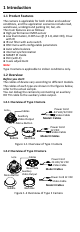
1 Introduction 1.1 Product Features The camera is applicable for both indoor and outdoor conditions, and the application scenarios include road, warehouse, underground parking lot, bar, etc. The main features are as follows: High performance CMOS sensor Low illumination, 0.005 Lux @ (F 1.
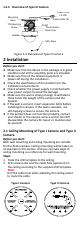
1.2.3 Overview of Type III Camera Mounting Base Tilt Adjusting Screw Power Cord 12 VDC Video Cable TVI IR LED Photoresistor Black Liner Bubble Safty Rope Figure 1-3 Overview of Type III Camera 2 Installation Before you start: Make sure that the device in the package is in good condition and all the assembly parts are included. Make sure that all the related equipment is power-off during the installation. Check the specification of the products for the installation environment.
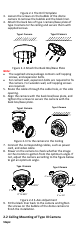
Figure 2-1 The Drill Template 3. Loosen the screws on the bubble of the dome camera to remove the bubble and the black liner. 4. Attach the back box of type I camera/base plate of type II camera to the ceiling and secure them with supplied screws. Type I Camera Type II Camera Figure 2-2 Attach the Back Box/Base Plate Note: The supplied screw package contains self-tapping screws, and expansion bolts. For cement wall, expansion bolts are required to fix the camera.
1. Paste the dill template to the ceiling. 2. Drill the screw holes and cable hole (optional) in the ceiling according to the drill template. Note: Cable hole is required, when adopting the ceiling outlet to route cables. 1 1 A Drill Template Hole A: for cables routed through the ceiling screw hole 1: for Mounting Base 1 Figure 2-5 Drill Template 3. Loosen the set screws with a hex wrench (supplied) to remove the bubble. Figure 2-6 Remove the Bubble 4.
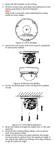
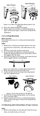
0° to 355° Adjusting Screw 0° to 75° 0° to 355° Figure 2-8 Type I Camera 2-Axis Adjustment 1) Loosen the tilt adjusting screw to adjust the tilt position [0° to 75°]. 2) Hold the black liner to adjust the pan position [0° to 355°]. 3) Hold the camera body to adjust the rotation position [0° to 355°] 8. Reinstall the bubble, and tighten the screws. Figure 2-9 Bubble Reinstallation 2.
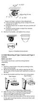
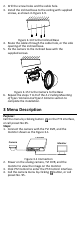
Type II Camera Type I Camera Figure 2-11 Attach the Back Box/Base Plate to the Bracket 6. Route the cables through the bracket. 7. Repeat steps 6 to 9 of the 2.1 Ceiling Mounting of Type I Camera and Type II Camera to complete the installation. 2.4 In-Ceiling Mounting Befor you start: You need to purchase an in-ceiling mounting bracket separately. Steps: 1. Attach the in-ceiling mounting bracket on the wall and mark the screw holes, and cable holes on the wall. 2.
2. Drill the screw holes and the cable hole. 3. Install the inclined base to the ceiling with supplied screws, as shown in Figure 2-9. Figure 2-14 Fix the Inclined Base 4. Route the cables through the cable hole, or the side opening of the inclined base. 5. Fix the camera to the inclined base with the supplied screws. Figure 2-15 Fix the Camera to the Base 6. Repeat the steps 7 to 9 of the 2.1 Ceiling Mounting of Type I Camera and Type II Camera section to complete the installation.
BRIGHTNESS EXPOSURE MODE AE AGC FORMAT SENSE UP MODE WB RETURN MODE DAY NIGHT RETURN MAIN MENU CONTRAST SHARPNESS VIDEO SETTINGS COLOR GAIN 3D DNR MIRROR LANGUAGE RETURN PRIVACY MOTION CAM ID FUNC RETURN FOCUS RESET SAVE & EXIT Figure 3-2 Main Menu Overview 5. Click the direction arrow to control the camera. 1) Click up/down direction button to select the item. 2) Click Iris + to confirm the selection. 3) Click left/right direction button to adjust the value of the selected item. 3.
BRIGHTNESS Brightness refers to the brightness of the image. You can set the brightness value from 1 to 10 to darken or brighten the image. The higher the value, the brighter the image is. EXPOSURE MODE You can set the EXPOSURE MODE as GLOBAL, BLC, and WDR. GLOBAL GLOBAL refers to the normal exposure mode which adjusts lighting distribution, variations, and non-standard processing.
3.4.3 DAY NIGHT Color, BW (Black White), and AUTO are selectable for DAY and NIGHT switches. COLOR The image is colored in day mode all the time. B/W The image is black and white all the time, and the IR LED turns on in the low-light conditions. AUTO You can turn on/off the INFRARED and set the value of SMART IR in this menu. DAY NIGHT MODE INFRARED SMART IR RETURN AUTO ON 4 Figure 3-5 DAY NIGHT INFRARED You can turn on/off the IR LED to meet the requirements of different circumstances.
H: The image flips 180° horizontally. V: The image flips 180° vertically. HV: The image flips 180° both horizontally and vertically. 3.4.5 FUNC (Functions) In the FUNC sub-menu, you can set the privacy mask, the motion detection, and camera ID of the camera. PRIVACY The privacy mask allows you to cover certain areas which you don’t want to be viewed or recorded. Up to 4 privacy areas are configurable.