TURBO HD D8T Series Turret Camera User Manual UD05330B User Manual Thank you for purchasing our product. If there are any questions, or requests, do not hesitate to contact the dealer. This manual applies to the models below: Type Model Type I Camera DS-2CE56D8T-IT1(E) Type II Camera DS-2CE56D8T-IT3(E) DS-2CE56D8T-ITM(E) This manual may contain technical incorrect places or printing errors, and the content is subject to change without notice.
Regulatory Information FCC Information Please take attention that changes or modification not expressly approved by the party responsible for compliance could void the user’s authority to operate the equipment. FCC compliance: This equipment has been tested and found to comply with the limits for a Class A digital device, pursuant to part 15 of the FCC Rules. These limits are designed to provide reasonable protection against harmful interference when the equipment is operated in a commercial environment.
Safety Instruction These instructions are intended to ensure that user can use the product correctly to avoid danger or property loss. The precaution measure is divided into “Warnings” and “Cautions”. Warnings: Serious injury or death may occur if any of the warnings are neglected. Cautions: Injury or equipment damage may occur if any of the cautions are neglected. Warnings Follow these safeguards to prevent serious injury or death.
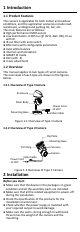
1 Introduction 1.1 Product Features The camera is applicable for both indoor and outdoor conditions, and the application scenarios include road, warehouse, underground parking lot, bar, etc.. The main features are as follows: High performance CMOS sensor Low illumination, 0.005 Lux @ (F2.0, AGC ON), 0 Lux with IR IR cut filter with auto switch OSD menu with configurable parameters Auto white balance Internal synchronization SMART IR mode PoC (with -E) 3-axis adjustment 1.
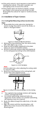
If the wall is cement, insert expansion screws before installing the camera. If the wall is wooden, use self-tapping screw to secure the camera. If the product does not function properly, contact your dealer or the nearest service center. Do NOT disassemble the camera for repair or maintenance by yourself. 2.1 Installation of Type I Camera 2.1.1 Ceiling/Wall Mounting without Junction Box Steps: 1.
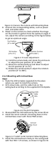
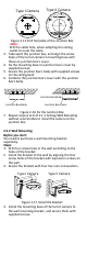
Figure 2-4 Secure the Camera with Mounting Base 8. Connect the corresponding cables, such as power cord, and video cable. 9. Power on the camera to check whether the image on the monitor is gotten from the optimum angle. If not, adjust the camera according to the figure below to get an optimum angle. Pan Position [0° to 360°] Tilt Position [0°to 75°] Rotation Position [0°to 360°] Figure 2-5 3-axis Adjustment 1). Hold the camera body and rotate the enclosure to adjust the pan position [0° to 360°]. 2).
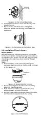
Inclined Base Body Figure 2-8 Fix the Inclined Base Body 6. Combine inclined base’s cover with its body with supplied screws. 7. Repeat steps 6 to 9 of the 2.1.1 Ceiling/Wall Mounting without Junction Box to complete the installation. Figure 2-9 Fix the Camera to the Inclined Base 2.2 Installation of Type II Camera Before you start: Both wall mounting and ceiling mounting are suitable for the turret camera. Ceiling mounting will be taken as an example in this section.
5. Note: Drill the cable hole in the center of the drill template, when adopting the ceiling outlet to route the cable. Secure the mounting base to the ceiling with the supplied screws. Expansion Bolts Fixing Screw Figure 2-12 Fix the Mounting Base to the Ceiling Note: The supplied screw package contains self-tapping screws, and expansion bolts. For cement wall/ceiling, expansion bolts are required to fix the camera. For wooden wall/ceiling, self-tapping screws are required. 6.
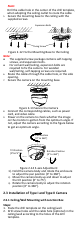
Type I Camera 3. 4. 5. 6. Type II Camera Figure 2-15 Drill Template of the Junction Box Note: Drill the cable hole, when adopting the ceiling outlet to route the cable. Take apart the junction box, and align the screw holes of the turret camera’s mounting base with those on junction box’s cover. Fix the mounting base on junction box’s cover by supplied screws. Secure the junction box’s body with supplied screws on the ceiling/wall. Combine the junction box’s cover with the junction box’s body.
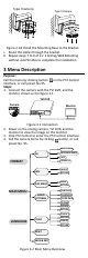
Type I Camera Type II Camera Figure 2-18 Install the Mounting Base to the Bracket Route the cables through the bracket. 6. Repeat steps 7 to 9 of 2.1.1 Ceiling/Wall Mounting without Junction Box to complete the installation. 5. 3 Menu Description Purpose: Call the menu by clicking button on the PTZ Control interface, or call preset No.95. Steps: 1. Connect the camera with the TVI DVR, and the monitor, shown as the figure 3-1. TVI DVR Camera Monitor Figure 3-1 Connection 2.
5. Click the direction arrow to control the camera. (1) Click up/down direction button to select the item. (2) Click Iris + to confirm the selection. (3) Click left/right direction button to adjust the value of the selected item. 3.1 FORMAT PAL (Phase Alternating Lines) PAL is a color encoding system for analog television used in broadcast television systems in most countries.
SENSE UP Sense up increases the exposure on a signal frame, which makes a camera more sensitive to light so it can produce images even in low lux conditions. You can set the SENS-UP as OFF or AUTO according to different light conditions. The SENS-UP function will atomically adjust itself to x2, x4, x6, x8, x10, x12, x14, and x16 according to the different light conditions. 3.3.
3.3.4 VIDEO SETTING Move the cursor to VIDEO SETTING and click Iris+ to enter the submenu. CONTRAST, SHARPNESS, COLOR GAIN, 3D DNR, and MIRROR are adjustable. VIDEO SETTING CONTRAST SHARPNESS COLOR GAIN 3D DNR MIRROR 5 5 5 5 DEFAULT RETURN Figure 3-6 VIDEO SETTING CONTRAST This feature enhances the difference in color and light between parts of an image. You can set the CONTRAST value from 1 to 10. SHARPNESS Sharpness determines the amount of detail an imaging system can reproduce.
be triggered. Up to 4 motion detection areas can be configured. MOTION MODE AREA 0 AREA 1 AREA 2 AREA 3 SENSITIVITY COLOR TRANSPARENCY RETURN OFF 50 RED OFF Figure 3-8 MOTION Select a MOTION area. Set the DISPLAY status as ON. Click the up/down/left/right button to define the position and size of the area. Set the SENSITIVITY from 0 to 100. CAMERA ID Edit the camera ID on this section.