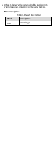
TURBO HD D0T Bullet & Turret & Dome Camera User Manual User Manual Thank you for purchasing our product. If there are any questions, or requests, do not hesitate to contact the dealer. This manual applies to the model listed below. Type Model Type I DS-2CE16D0T-VFIR3E Type II DS-2CE56D0T-VFIR3E Type III DS-2CE56D0T-VPIR3E Type IV DS-2CE56D0T-VFIRE This manual may contain several technically incorrect places or printing errors, and the content is subject to change without notice.
Regulatory Information FCC Information FCC compliance: This equipment has been tested and found to comply with the limits for a Class A digital device, pursuant to part 15 of the FCC Rules. These limits are designed to provide reasonable protection against harmful interference when the equipment is operated in a commercial environment.
Safety Instruction These instructions are intended to ensure that user can use the product correctly to avoid danger or property loss. The precaution measure is divided into “Warnings” and “Cautions”. Warnings: Serious injury or death may occur if any of the warnings are neglected. Cautions: Injury or equipment damage may occur if any of the cautions are neglected. Warnings Follow these safeguards to prevent serious injury or death.
While in delivery, the camera shall be packed in its original packing, or packing of the same texture.
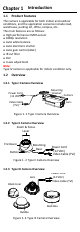
Introduction 1.1 Product Features The camera is applicable for both indoor and outdoor conditions, and the application scenarios include road, warehouse, parking lot, office, campus, etc.. The main features are as follows: High performance CMOS sensor 1080p resolution Auto white balance Auto electronic shutter Auto gain control (AGC) IR cut filter PoC 3-axis adjustment Note: Type IV camera is applicable for indoor condition only. 1.2 Overview 1.2.
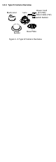
1.2.4 Type IV Camera Overview Black Liner Bubble Lens Power Cord (12 VDC) Video Cable (TVI) Switch Button Base Plate Figure 1.
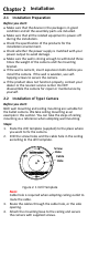
Installation 2.1 Installation Preparation Before you start: Make sure that the device in the package is in good condition and all the assembly parts are included. Make sure that all the related equipment is power-off during the installation. Check the specification of the products for the installation environment. Check whether the power supply is matched with your power output to avoid damage.
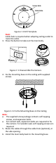
Figure 2. 2 Secure the Camera to the Ceiling Note: The supplied screw package contains self-tapping screws, and expansion bolts. For cement wall, expansion bolts are required to fix the camera. For wooden wall, self-tapping screws are required. 5. Connect the corresponding power cord and video cable. 6. Power on the camera to check whether the image on the monitor is gotten from the optimum angle. If not, adjust the camera according to the figure below to get an optimum angle.
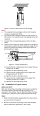
Screw Hole Cable Hole Figure 2. 4 Drill Template Note: Cable hole is required when adopting ceiling outlet to route the cable. 3. Press the button to take out the main body. Press Figure 2. 5 Disassemble the Camera 4. Fix the mounting base on the ceiling with supplied screws. Figure 2. 6 Fix the Mounting Base on the Ceiling Note: The supplied screw package contains self-tapping screws, and expansion bolts. For cement wall, expansion bolts are required to fix the camera.
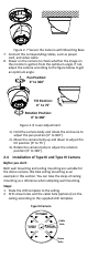
Figure 2. 7 Secure the Camera with Mounting Base 7. Connect the corresponding cables, such as power cord, and video cable. 8. Power on the camera to check whether the image on the monitor is gotten from the optimum angle. If not, adjust the camera according to the figure below to get an optimum angle. Pan Position: 0° to 360° Tilt Position: 0° to 75° Rotation Position: 0° to 360° Figure 2. 8 3-axis Adjustment 1). Hold the camera body and rotate the enclosure to adjust the pan position [0° to 360°]. 2).
Type IV Camera Screw Hole Cable Hole Figure 2. 9 The Drill Template Note: Cable hole is required when adopting ceiling outlet to Route the cable. 3. Loosen the bubble of the dome camera to remove the bubble and the black liner. 4. Attach the back box of type III camera/base plate of type IV camera to the ceiling and secure them with supplied screws. Type III Camera Type IV Camera Figure 2.
8. Power on the camera to check whether the image on the monitor is gotten from the optimum angle. If not, adjust the camera according to the figure below to get an optimum angle. Type III Camera Pan Position: 0° to 355° Tilt Position: 0° to 75° Rotation Position: 0° to 355° Type IV Camera Pan Position: 0 ° to 355 ° Tilt Position: 0 ° to 75 ° Rotation Position: 0 ° to 355 ° Figure 2. 12 3-axis Adjustment 9.