
Owners manual


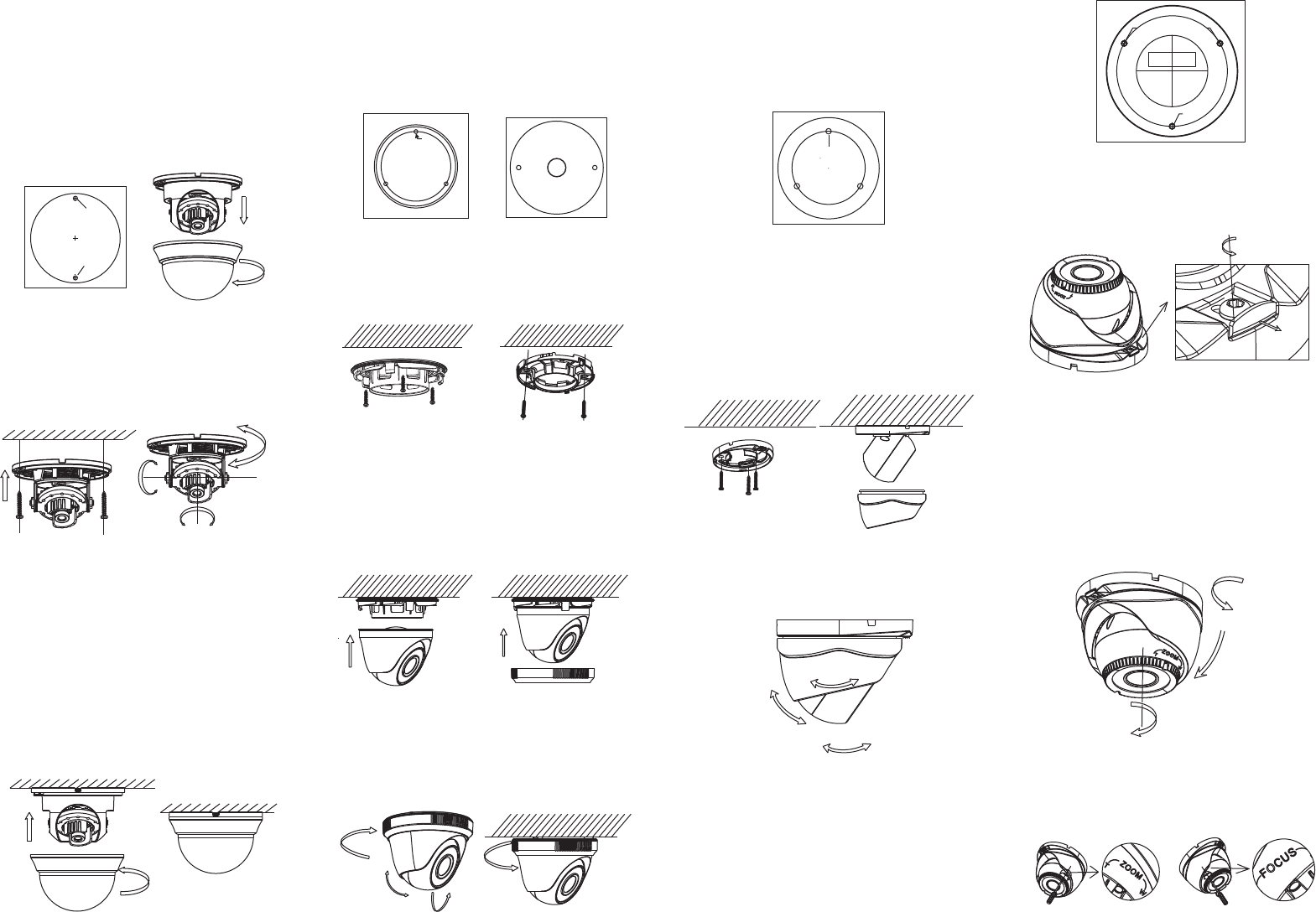
1.Hold the mounting base, and rotate the lower
dome counterclockwise to disassemble the
lower dome and the black liner.
2.Drill the screw holes and the cable hole the
ceiling according to the supplied drill template.
on
Steps:
Figure 2-1 The Disassembling
2.1 Ceiling Mounting for Type I
Camera
3.Route the cables to the cable hole and
the corresponding power cable and video cable.
4.Fix the mounting base to the ceiling with
the supplied screws.
connect
6.Fit the black liner back to the camera.
7.Install the lower dome back to the camera and
rotate it clockwise to get it secured.
Figure 2-2 3-axis Adjustment
5.Adjust the Lens
1).Loosen the tilting lock screws besides the
lens.
2).Adjust the camera from the pan angle
( ); tilt angle (0 ~ 90 ), and rotate
the lens(0 ~355 ) to get the optimum angle.
3).Tighten the tilting lock screws.
0° ~ 355° ° °
° °
Steps:
1.Drill the screw holes and the cable hole
according to the drill template.
Figure 2-5 Fix the Mounting Base
2.Fix the mounting base to the ceiling with the
supplied screws.
connect
3.Route the cables to the cable hole and
the corresponding power cable and video cable.
4.Secure the camera to the mounting base.
5.Fix the enclosure to camera to complet the
installation..
Figure 2-6 Fix the Components
Figure 2-4 Drill Template of Type Ⅱ/ CameraⅢ
Camera
2.2 Ceiling Mounting for Type II/ III
6.Adjust the surveillance angle according to the
figure below.
7.Rotate the trim ring clockwise to secure the
camera.
Figure 2-12 The Lock Screw
Figure 2-7 3-axis Adjustment
2.3 Ceiling Mounting for Type IV
Camera
2.Loosen the lock screw to disassemble the
camera from the mounting base.
Steps:
1.Drill the screws holes and the cable hole on the
ceiling according to the supplied drill template.
ix3.F the mounting base to the ceiling.
4.Route the cables to the cable hole and connect
the corresponding cables.
5.Secure the camera to the mounting base by
tightening the lock screw.
6.Adjust the camera according to the figure
below to get an optimum angle.
Figure 2-13 3-axis Adjustment
7.Use the screwdriver to adjust the ZOOM screw
and the FOCUS screw until you get the
optimum image.
Figure 2-14 Zoom and Focus Adjustment
Figure 2-3 Complete the Installation
Steps:
1.Drill the screw holes and the cable hole
according to the drill template.
Figure 2-8 The Drill Template of Type IV Camera
2.Fix the mounting base to the ceiling with the
supplied screws.
Figure 2-9 Fix the Mounting Base and the Camera
6.Adjust the camera according to the figure below
to get an optimum angle.
3.Route the cables to the cable hole and
corresponding power cable and video cable.
4.Secure the camera to the mounting base.
5.Fix the enclosure to camera to complete the
installation.
connect
Figure 2-10 3-axis Adjustment
2.4 Ceiling Mounting for Type V
Camera
Figure 2-11 The Drill Template of Type V Camera
355°
355°
0-90°
P 0° ~ an 360°
Tilt 0° ~ 75°
Rotation 0° ~ 360°
Template
Screw Hole
Screw Hole
Screw Hole
Hole
Ceiling Mounting
Hole
Screw Hole
Drilling Template
Screw Hole
Screw Hole
Screw Hole
360°
360°
0 ~ 75°
360°
360°
0 ~ 75°