TURBO HD H8T Series Bullet & Turret Camera User Manual User Manual Thank you for purchasing our product. If there are any questions, or requests, do not hesitate to contact the dealer. This manual applies to the models below: Type Model Type I Camera DS-2CE19H8T-(A)IT3ZF Type II Camera DS-2CE79H8T-IT3ZF This manual may contain technical incorrect places or printing errors, and the content is subject to ch8ange without notice. The updates will be added to the new version of this manual.
Regulatory Information FCC Information Please take attention that changes or modification not expressly approved by the party responsible for compliance could void the user’s authority to operate the equipment. FCC compliance: This equipment has been tested and found to comply with the limits for a Class A digital device, pursuant to part 15 of the FCC Rules. These limits are designed to provide reasonable protection against harmful interference when the equipment is operated in a commercial environment.
Safety Instruction These instructions are intended to ensure that user can use the product correctly to avoid danger or property loss. The precaution measure is divided into “Warnings” and “Cautions”. Warnings: Serious injury or death may occur if any of the warnings are neglected. Cautions: Injury or equipment damage may occur if any of the cautions are neglected. Warnings Follow these safeguards to prevent serious injury or death.
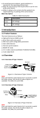
To avoid heat accumulation, good ventilation is required for the operating environment. Keep the camera away from liquid while in use for nonwater-proof device. While in delivery, the camera shall be packed in its original packing, or packing of the same texture. Mark Description Table 0-1 Mark Description Mark Description DC Voltage AC Voltage 1 Introduction 1.
2 Installation Before you start: Make sure that the device in the package is in good condition and all the assembly parts are included. Make sure that all the related equipment is power-off during the installation. Check the specification of the products for the installation environment. Check whether the power supply is matched with your power output to avoid the damage. Make sure the wall is strong enough to withstand three times the weight of the camera and the mount.
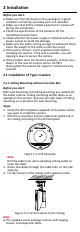
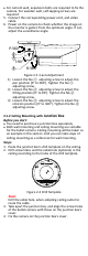
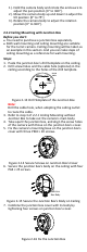
For cement wall, expansion bolts are required to fix the camera. For wooden wall, self-tapping screws are required. 5. Connect the corresponding power cord, and video cable. 6. Power on the camera to check whether the image on the monitor is gotten from the optimum angle. If not, adjust the surveillance angle. P:360° 1 2 T:90° 3 R:360° Figure 2-3 3-axis Adjustment 1) Loosen the No.① adjusting screw to adjust the pan position [0° to 360°]. Tighten the No.① adjusting screw. 2) Loosen the No.
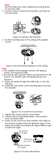
Figure 2-5 Fix the Camera with the Junction Box 5. Attach the junction box’s body to the ceiling by aligning the screw holes of the junction box. 6. Secure the junction box’s body with supplied screws on the ceiling. Junction Box Body Screw Figure 2-6 Fix the Camera to the Ceiling 7. Route the cables through the cable hole, or the side opening of the junction box. 8. Combine the junction box cover with its body. Figure 2-7 Fix the Junction Box Cover back to its Body 9. Refer to step 6 of 2.1.
Note: Drill the cable hole, when adopting the ceiling outlet to route the cable. 3. Loosen screws to remove the clip plate, and take out the main body. Clip Plate Figure 2-9 Remove the Clip Plate 4. Fix the mounting base on the ceiling with supplied screws. Figure 2-10 Fix the Mounting Base on the Ceiling Note: The supplied screw package contains self-tapping screws, and expansion bolts. For cement wall, expansion bolts are required to fix the camera.
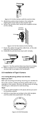
1). Hold the camera body and rotate the enclosure to adjust the pan position [0° to 360°]. 2). Move the camera body up and down to adjust the tilt position [0° to 75°]. 3). Rotate the camera body to adjust the rotation position [0° to 360°]. 2.2.2 Ceiling Mounting with Junction Box Before you start: You need to purchase a junction box separately. Both wall mounting and ceiling mounting are suitable for the turret camera. Ceiling mounting will be taken as an example in this section.
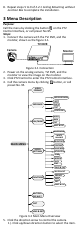
8. Repeat steps 5 to 9 of 2.2.1 Ceiling Mounting without Junction Box to complete the installation. 3 Menu Description Purpose: Call the menu by clicking the button on the PTZ Control interface, or call preset No.95. Steps: 1. Connect the camera with the TVI DVR, and the monitor, shown as the figure 3-1. TVI DVR Camera Monitor Figure 3-1 Connection 2. Power on the analog camera, TVI DVR, and the monitor to view the image on the monitor. 3. Click PTZ Control to enter the PTZ Control interface. 4.
2). Click Iris + to confirm the selection. 3). Click left/right direction button to adjust the value of the selected item. 3.1 VIDOE FORMAT You can set the video format as 5MP@20fps, 4MP@25fps, 4MP@30fps, 2MP@25fps, and 2MP@30fps. Note: When switching the video output as CVBS, you can set the video format as PAL, or NTSC. When switching the video output as AHD, 5MP@20fps, 4MP@25fps, and 4MP@30fps are supported.
You can turn on/off the IR LIGHT and set the value of SMART IR in this menu DAY/NIGHT MODE IR LIGHT SMART IR BACK EXIT SAVE & EXIT B&W ON 2 Figure 3-4 B & W IR LIGHT You can turn on/off the IR LIGHT to meet the requirements of different circumstances. SMART IR The Smart IR function is used to adjust the light to its most suitable intensity, and prevent the image from over exposure. The SMART IR value can be adjusted from 0 to 3. The higher the value is, the more obvious effects are.
VIDEO SETTINGS IMAGE MODE WHITE BALANCE BRIGHTNESS CONTRAST SHARPNESS SATURATION 3DNR MIRROR BACK EXIT SAVE & EXIT STD 5 5 5 5 5 OFF Figure 3-6 VIDEO SETTINGS IMAGE MODE IMAGE MODE is used to adjust the image saturation, and you can set it as STD (Standard), or HIGH-SAT (High Saturation). WHITE BALANCE White balance, the white rendition function of the camera, is to adjust the color temperature according to the environment. It can remove unrealistic color casts in the image.
MIRROR OFF, H, V, and HV are selectable for mirror. OFF: The mirror function is disabled. H: The image flips 180° horizontally. V: The image flips 180° vertically. HV: The image flips 180° both horizontally and vertically. 3.5 FUNCTIONS In the FUNCTIONS submenu, you can set the motion detection, and privacy mask of the camera. MOTION DETECTION In the user-defined motion detection surveillance area, the moving object can be detected and the alarm will be triggered.