TURBO HD 4K Series Bullet Camera User Manual User Manual Thank you for purchasing our product. If there are any questions, or requests, do not hesitate to contact the dealer. This manual applies to the models below: Type Model Type I Camera DS-2CE17U8T-IT Type II Camera DS-2CE18U8T-IT3 This manual may contain several technical incorrect places or printing errors, and the content is subject to change without notice. The updates will be added to the new version of this manual.
Regulatory Information FCC Information Please take attention that changes or modification not expressly approved by the party responsible for compliance could void the user’s authority to operate the equipment. FCC compliance: This equipment has been tested and found to comply with the limits for a Class A digital device, pursuant to part 15 of the FCC Rules. These limits are designed to provide reasonable protection against harmful interference when the equipment is operated in a commercial environment.
Safety Instruction These instructions are intended to ensure that user can use the product correctly to avoid danger or property loss. The precaution measure is divided into “Warnings” and “Cautions”. Warnings: Serious injury or death may occur if any of the warnings are neglected. Cautions: Injury or equipment damage may occur if any of the cautions are neglected. Warnings Follow these safeguards to prevent serious injury or death.
To avoid heat accumulation, good ventilation is required for the operating environment. Keep the camera away from liquid while in use for non-water-proof device. While in delivery, the camera shall be packed in its original packing, or packing of the same texture. Mark Description Table 0-1 Mark Description Mark Description DC Voltage 1 Introduction 1.
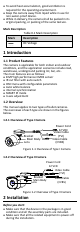
Check the specification of the products for the installation environment. Check whether the power supply is matched with your power output to avoid the damage. Make sure the wall is strong enough to withstand three times the weight of the camera and the mount. If the wall is cement, insert expansion bolts before installing the camera. If the wall is wooden, use self-tapping screws to secure the camera. If the product does not function properly, contact your dealer or the nearest service center.
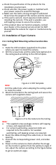
Pan Position [0° to 360°] Rotation Position [0° to 360°] P Screw Tilt Position [0° to 180°] T Screw R Screw Figure 2-3 3-axis Adjustment 1). Loosen the P screw to adjust the pan position [0° to 360°]. Tighten the screw after completing the adjustment. 2). Loosen the T screw to adjust the tilt position [0° to 180°]. Tighten the screw after completing the adjustment. 3). Loosen the R screw and rotate the camera [0° to 360°]. Tighten the screw after completing the adjustment. 2.1.
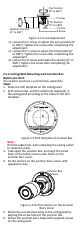
Junction Box Body Figure 2-6 Fix the Junction Box to the Wall/Ceiling 7. Route the cables through the bottom cable hole (optional), or the side cable hole of the junction box. 8. Combine the junction box cover with its body. Figure 2-7 Fix the Junction Box Cover back to its Body 9. Repeat the step 5 and 6 of 2.1.1 Ceiling/Wall Mounting without Junction Box to complete the installation. 2.2 Installation of Type II Camera 2.2.1 Ceiling/Wall Mounting without Junction Box Steps: 1.
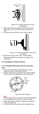
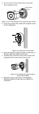
Figure 2-9 Fix the Camera to the Ceiling Note: The supplied screw package contains self-tapping screws, and expansion bolts. For cement wall/ceiling, expansion bolts are required to fix the camera. For wooden wall/ceiling, self-tapping screws are required. 5. Connect the corresponding power cord, and video cable. 6. Power on the camera to check whether the image on the monitor is gotten from the optimum angle. If not, adjust the surveillance angle.
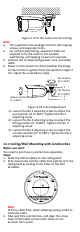
4. Fix the camera on the junction box’s cover with three supplied screws. Junction Box Cover Figure 2-11 Fix the Camera on the Junction Box’s Cover 5. Secure the junction box’s body with supplied screws on the ceiling/wall. Figure 2-12 Install the Junction Box 6. Route the cables through the bottom cable hole, or the side cable hole of the junction box. 7. Combine the junction box cover with its body with supplied screws on the junction box’s cover.
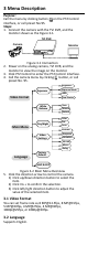
3 Menu Description Purpose: Call the menu by clicking button on the PTZ Control interface, or call preset No.95. Steps: 1. Connect the camera with the TVI DVR, and the monitor shown as the Figure 3-1. TVI DVR Camera Monitor Figure 3-1 Connection 2. Power on the analog camera, TVI DVR, and the monitor to view the image on the monitor. 3. Click PTZ Control to enter the PTZ Control interface. 4. Call the camera menu by clicking button, or call preset No. 95.
3.3 Settings 3.3.1 Exposure Exposure describes the brightness-related parameters, which can be adjusted by Brightness, Exposure Mode, AGC, and Slow Shutter. Exposure Brightness Exposure Mode AGC Slow Shutter Back <5> Save & Exit Figure 3-3 Exposure Brightness Brightness refers to the brightness of the image. You can set the brightness value from 1 to 10 to darken or brighten the image. The higher the value is, the brighter the image is.
3.3.2 WB (White Balance) White balance, the white rendition function of the camera, is to adjust the color temperature according to the environment. It can remove unrealistic color casts in the image. You can set WB mode as Auto, Manual, or Natural. Auto Under Auto mode, white balance is being adjusted automatically according to the color temperature of the scene illumination.
Day to Night Threshold is used to control the sensitivity of switching the day mode to the night mode. You can set the value from 1 to 9. The larger the value is, the more sensitive the camera is. Nà D Threshold (Night to Day Threshold) Night to Day Threshold is used to control the sensitivity of switching the night mode to the day mode. You can set the value from 1 to 9. The larger the value is, the more sensitive the camera is. 3.3.
3.3.5 Facroty Default Click Iris+ to enter the submenu, and click OK to reset all the settings to the factory default. Click Cancel to give up the reset settings. 3.3.6 Save & Exit Move the cursor to Save & Exit, and click Iris+ to save the settings and exit the menu.