TURBO HD H5T Series Bullet Camera User Manual UD05381B User Manual Thank you for purchasing our product. If there are any questions, or requests, do not hesitate to contact the dealer. This manual applies to the models below: Type Model Type I Camera DS-2CE16H5T-IT(E) DS-2CE16H5T-ITP(E) DS-2CE16H5T-IT1(E) Type II Camera DS-2CE16H5T-IT3(E) DS-2CE16H5T-IT5(E) This manual may contain several technical incorrect places or printing errors, and the content is subject to change without notice.
Regulatory Information FCC Information Please take attention that changes or modification not expressly approved by the party responsible for compliance could void the user’s authority to operate the equipment. FCC compliance: This equipment has been tested and found to comply with the limits for a Class A digital device, pursuant to part 15 of the FCC Rules. These limits are designed to provide reasonable protection against harmful interference when the equipment is operated in a commercial environment.
Safety Instruction These instructions are intended to ensure that user can use the product correctly to avoid danger or property loss. The precaution measure is divided into “Warnings” and “Cautions”. Warnings: Serious injury or death may occur if any of the warnings are neglected. Cautions: Injury or equipment damage may occur if any of the cautions are neglected. Warnings Follow these safeguards to prevent serious injury or death.
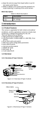
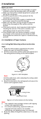
Keep the camera away from liquid while in use for non-water-proof device. While in delivery, the camera shall be packed in its original packing, or packing of the same texture. Mark Description Table 0-1 Mark Description Mark Description DC Voltage 1 Introduction 1.1 Product Features The camera is applicable for both indoor and outdoor conditions, and the application scenarios include road, warehouse, underground parking lot, bar, etc..
2 Installation Before you start: Make sure that the device in the package is in good condition and all the assembly parts are included. Make sure that all the related equipment is power-off during the installation. Check the specification of the products for the installation environment. Check whether the power supply is matched with your power output to avoid the damage. Make sure the wall is strong enough to withstand three times the weight of the camera and the bracket.
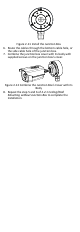
5. Connect the corresponding power cord, and video cable. 6. Power on the camera to check whether the image on the monitor is gotten from the optimum angle. If not, adjust the camera according to the figure below to get an optimum angle. Pan Position [0° to 360°] Rotation Position [0° to 360°] P Screw Tilt Position [0° to 180°] T Screw R Screw Figure 2-3 3-axis Adjustment 1). Loosen the P screw to adjust the pan position [0° to 360°]. Tighten the screw after completing the adjustment. 2).
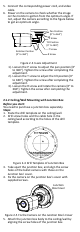
6. Secure the junction box’s body with supplied screws on the ceiling/wall. Junction Box Body Figure 2-6 Fix the Junction Box to the Wall/Ceiling 7. Route the cables through the bottom cable hole, or the side cable hole of the junction box. 8. Combine the junction box cover with its body. Figure 2-7 Fix the Junction Box Cover back to its Body 9. Repeat the step 5 and 6 of 2.1.1 Ceiling/Wall Mounting without Junction Box to complete the installation. 2.2 Installation of Type II Camera 2.2.
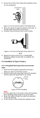
Figure 2-9 Fix the Camera to the Ceiling Note: The supplied screw package contains self-tapping screws, and expansion bolts. For cement wall/ceiling, expansion bolts are required to fix the camera. For wooden wall/ceiling, self-tapping screws are required. 5. Connect the corresponding power cord, and video cable. 6. Power on the camera to check whether the image on the monitor is gotten from the optimum angle. If not, adjust the surveillance angle.
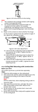
Figure 2-11 Install the Junction Box 6. Route the cables through the bottom cable hole, or the side cable hole of the junction box. 7. Combine the junction box cover with its body with supplied screws on the junction box’s cover. Figure 2-12 Combine the Junction Box’s Cover with its Body 8. Repeat the step 5 and 6 of 2.2.1 Ceiling/Wall Mounting without Junction Box to complete the installation.
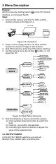
3 Menu Description Purpose: Call the menu by clicking button on the PTZ Control interface, or call preset No.95. Steps: 1. Connect the camera with the TVI DVR, and the monitor, shown as the figure 3-1. TVI DVR Camera Monitor Figure 3-1 Connection 2. Power on the analog camera, TVI DVR, and the monitor to view the image on the monitor. 3. Click PTZ Control to enter the PTZ Control interface. 4. Call the camera menu by clicking button, or call preset No. 95.
OUTPUT MODE RESOLUTION FRAME RATE NTSC/PAL APPLY BACK 5 MEGA 12.5 FPS PAL Figure 3-3 OUTPUT MODE RESOLUTION Resolution refers to the number of the pixels contained in an image. You can set the resolution as 5 megapixels, 4 megapixels or 1080p. The higher the value, the finer the image is. FRAME RATE Frame rate refers to the number of image output in 1 second. When the resolution is set as 5 megapixels, you are allowed to set the frame rate as 20 fps or 12.5 fps.
BLC (Backlight Compensation) BLC (Backlight Compensation) compensates light for the front object to make it clear, but this may cause the over-exposure of the background, where the light is strong. When BLC is selected as the exposure mode, the BLC level can be adjusted from 0 to 8. GAIN It optimizes the clarity of the image in poor light conditions. The GAIN level can be set as HIGH, MEDIUM, or LOW. Select OFF to disable the GAIN function. Note: The noise will be amplified, when the GAIN is on.
You can turn on/off the INFRARED and set the value of SMART IR in this menu. DAY/NIGHT MODE INFRARED SMART IR BACK AUTO ON 1 Figure 3-6 DAY/NIGHT INFRARED You can turn on/off the IR LED to meet the requirements of different circumstances. SMART IR The Smart IR function is used to adjust the light to its most suitable intensity, and prevent the image from over exposure. The SMART IR value can be adjusted from 1 to 3. The higher the value, the more obvious effects are. 3.
3.7 RESET Reset all the settings to the default. 3.8 SAVE & EXIT Move the cursor to SAVE & EXIT and click Iris+ to save the setting and exit the menu.