
User Manual

UM DS-2CEx6H0T-xxITxF 042618NA 9
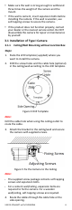
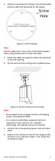
2. Drill the screw holes according to the drill template
and the cable hole (optional) on the ceiling.
Figure 11 Drill Template
Note:
Drill the cable hole in the center of the drill template
when using ceiling outlet to route the cable.
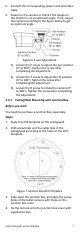
3. Route the cables through the cable hole (optional)
or the side opening.
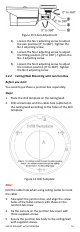
4. Fix the camera to the ceiling with supplied screws.
Figure 12 Fix the Camera to the Ceiling
Note:
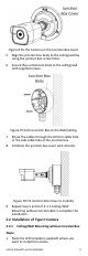
•
The supplied screw package contains self-tapping
screws, and expansion bolts.
•
For a cement wall/ceiling, expansion bolts are
required to fix the camera. For a wooden
wall/ceiling, self-tapping screws are required.
5. Connect the corresponding power cord and video
cable.
6. Power on the camera to check if the image on the
monitor is at an optimum angle. If not, adjust the
surveillance angle.