
User Manual

UM DS-2CEx6H0T-xxITxF 042618NA 7
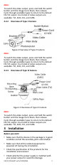
5. Connect the corresponding power cord and video
cable.
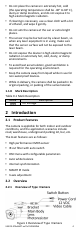
6. Power on the camera to check if the image on
the monitor is at an optimum angle. If not, adjust
the camera according to the figure below to get
an optimum angle.
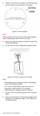
Figure 6 3-axis Adjustment
1). Loosen the P screw to adjust the pan position
[0° to 360°]. Tighten the screw after
completing the adjustment.
2). Loosen the T screw to adjust the tilt position
[0° to 180°]. Tighten the screw after
completing the adjustment.
3). Loosen the R screw to rotate the camera [0°
to 360°]. Tighten the screw after completing
the adjustment.
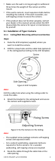
3.1.2 Ceiling/Wall Mounting with Junction Box
Before you start:
You need to purchase a junction box separately.
Steps:
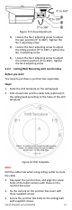
1. Paste the drill template on the ceiling/wall.
2. Drill screw holes and the cable hole in the
ceiling/wall according to the holes of the drill
template.
Figure 7 Junction Box Drill Template
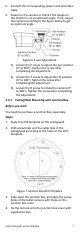
3. Take apart the junction box, and align the screw
holes of the bullet camera with those on the
junction box cover.
4. Fix the camera onto the junction box cover with
supplied screws.