TurboHD DS-2CE11H0T-PIRL Bullet Camera User Manual Thank you for purchasing our product. If there are any questions, or requests, do not hesitate to contact the dealer. This manual may contain several technical incorrect places or printing errors, and the content is subject to change without notice. Updates will be added to new versions of this manual. We will readily improve or update the products or procedures described in the manual. UM D-2CE11H0T-PIRL 2018 Hikvision USA Inc.
1 Regulatory Information 1.1 FCC Information Please take attention that changes or modification not expressly approved by the party responsible for compliance could void the user’s authority to operate the equipment. FCC Compliance: This equipment has been tested and found to comply with the limits for a Class A digital device, pursuant to part 15 of the FCC Rules.
Warnings Follow these safeguards to prevent serious injury or death. 1.7 Cautions Follow these precautions to prevent potential injury or material damage. Warnings • In the use of the device, you must be in strict compliance with the electrical safety regulations of the nation and region. • Input voltage should meet both the SELV (Safety Extra Low Voltage) and the Limited Power Source with 12 VDC according to the IEC60950-1 standard. Refer to technical specifications for detailed information.
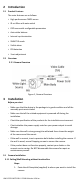
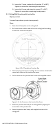
2 Introduction 2.1 Product Features The main features are as follows: • High performance CMOS sensor • IR cut filter with auto switch • OSD menu with configurable parameters • Auto white balance • Internal synchronization • SMART IR mode • Visible alarm • PIR detection • 3-axis adjustment 2.2 Overview 2.2.1 Camera Overview Figure 1, Camera Overview 3 Installation Before you start • Make sure that the device in the package is in good condition and all the assembly parts are included.
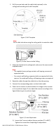
2. Drill the screw holes and the cable hole (optional) in the ceiling/wall according to the drill template. Figure 2, Drill Template Note: Drill a cable hole when using the ceiling outlet to route the cable. Figure 3, Fix the Camera to the Ceiling 3. Attach the bracket to the ceiling/wall, and secure the camera with supplied screws. Note: • The supplied screw package contains self-tapping screws and expansion bolts. • For cement wall/ceiling, expansion bolts are required to fix the camera.
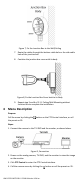
2). Loosen the T screw to adjust the tilt position [0° to 180°]. Tighten the screw after completing the adjustment. 3). Loosen the R screw and rotate the camera [0° to 360°]. Tighten the screw after completing the adjustment. 3.1.2 Ceiling/Wall Mounting with Junction Box Before you start: You need to purchase a junction box separately. Steps: 1. Paste the drill template on the ceiling/wall. 2. Drill screw holes and the cable hole in the ceiling/wall according to the holes of the drill template.
Figure 7, Fix the Junction Box to the Wall/Ceiling 7. Route the cables through the bottom cable hole or the side cable hole of the junction box. 8. Combine the junction box cover with its body. Figure 8, Fix the Junction Box Cover back to its Body 9. Repeat step 5 and 6 of 2.1.1 Ceiling/Wall Mounting without Junction Box to complete the installation. 4 Menu Description Purpose: Call the menu by clicking the the preset no.95. button on the PTZ Control interface, or call Steps: 1.
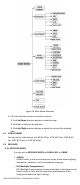
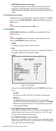
Figure 10, Main Menu Overview 5. Click the direction arrow to control the camera. 1). Click Up/Down direction button to select the item. 2). Click Iris+ to confirm the selection. 3). Click Left/Right direction button to adjust the value of the selected item. 4.1 VIDEO FORMAT You can set the video format to 5 MP @ 20 fps, 4 MP @ 25 fps, 4 MP @ 30 fps, 2 MP @ 25 fps, or 2 MP @ 30 fps. 4.2 EXPOSURE 4.2.1 EXPOSURE MODE You can set the EXPOSURE MODE to GLOBAL, BLC, or DWDR.
• DWDR (Digital Wide Dynamic Range) The digital wide dynamic range helps the camera provide clear images even under backlight circumstances. WDR balances the brightness level of the whole image and provides clear images with details. 4.2.2 AGC (Auto Gain Control) It optimizes the clarity of the image in poor light conditions. The AGC level can be set as HIGH, MEDIUM, or LOW. Select OFF to disable the AGC function. Note: The noise will be amplified when the AGC is on. 4.2.
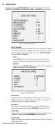
4.3 VIDEO SETTINGS Move the cursor to VIDEO SETTINGS and click Iris+ to enter the submenu. CONTRAST, SHARPNESS, COLOR GAIN, 3 DNR, and MIRROR are adjustable. Figure 12, VIDEO SETTING • WHITE BALANCE White balance, the white rendition function of the camera, adjusts the color temperature according to the environment. It can remove unrealistic color casts in the image. You can set WHITE BALANCE mode to AUTO or MANUAL.
• DNR (Digital Noise Reduction) The DNR function can decrease the noise effect, especially when capturing moving images in poor light conditions, and delivers more accurate and sharper images. You can set the DNR value from 1 to 9. • MIRROR OFF, H, V, and HV are selectable for mirror. OFF: The mirror function is disabled. H: The image flips 180° horizontally. V: The image flips 180° vertically. HV: The image flips 180° both horizontally and vertically. 4.
• LIGHTING Select the LIGHTING mode, the embedded white light source turns on in poor light conditions automatically. You can set the LIGHTING MODE to SOLID or FLASHING. ˗ SOLID The white light source turns on in poor lighting conditions. Figure 15, SOLID ˗ FLASHING When you set the LIGHTING MODE to FLASHING, you can set the TRIGGER MODE to CAMERA or DVR. The white light source flashes in poor lighting conditions when receiving the alarm signal. * TRIGGER MODE o DVR Set the TRIGGER MODE to DVR.
• EXIT Move the cursor to EXIT and click Iris+ to exit the menu. • SAVE & EXIT Move the cursor to SAVE & EXIT and click Iris+ to save the settings and exit the menu. UM D-2CE11H0T-PIRL 2018 Hikvision USA Inc.