
User Manual
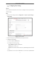
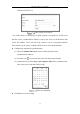

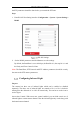


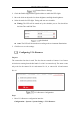


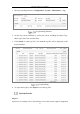
Table Of Contents
- Chapter 1 System Requirement
- Chapter 2 Network Connection
- Chapter 3 Access to the Network Camera
- Chapter 4 Live View
- Chapter 5 Network Camera Configuration
- Chapter 6 Network Settings
- Chapter 7 Video/Audio Settings
- Chapter 8 Image Settings
- Chapter 9 Event Settings
- 9.1 Basic Events
- 9.2 Smart Events
- 9.2.1 Configuring Audio Exception Detection
- 9.2.2 Configuring Defocus Detection
- 9.2.3 Configuring Scene Change Detection
- 9.2.4 Configuring Intrusion Detection
- 9.2.5 Configuring Line Crossing Detection
- 9.2.6 Configuring Region Entrance Detection
- 9.2.7 Configuring Region Exiting Detection
- 9.2.8 Configuring Unattended Baggage Detection
- 9.2.9 Configuring Object Removal Detection
- Chapter 10 Storage Settings
- Chapter 11 Playback
- Chapter 12 Picture
- Appendix

Network Camera User Manual
25
the PTZ parameters should be done before you control the PTZ unit.
Steps:
1. Enter RS-485 Port Setting interface: Configuration > System > System Settings >
RS485.
RS-485 Settings
2. Set the RS485 parameters and click Save to save the settings.
By default, the Baud Rate is set as 9600 bps, the Data Bit is 8, the stop bit is 1 and
the Parity and Flow Control is None.
Note: The Baud Rate, PTZ Protocol and PTZ Address parameters should be exactly
the same as the PTZ camera parameters.
Configuring Infrared Light
Purpose:
The camera has three sets of infrared lights which can be enabled or disabled
separately. The three sets of infrared lights are named as No.1 to No.3 clockwise
starting from the dial mark 0° to 240° on camera body. You can hover on the icon to
see the figure.
One-to-One Control: With one-to-one control enabled, you can bind certain set of
infrared light to certain camera channel. Thus the infrared light only works along with
the bound camera channel.