Network Camera User Manual Network Camera User Manual UD15501B 0
Network Camera User Manual User Manual COPYRIGHT ©2019 Hangzhou Hikvision Digital Technology Co., Ltd. ALL RIGHTS RESERVED. Any and all information, including, among others, wordings, pictures, graphs are the properties of Hangzhou Hikvision Digital Technology Co., Ltd. or its subsidiaries (hereinafter referred to be “Hikvision”).
Network Camera User Manual FITNESS FOR A PARTICULAR PURPOSE, AND NON-INFRINGEMENT OF THIRD PARTY. IN NO EVENT WILL HIKVISION, ITS DIRECTORS, OFFICERS, EMPLOYEES, OR AGENTS BE LIABLE TO YOU FOR ANY SPECIAL, CONSEQUENTIAL, INCIDENTAL, OR INDIRECT DAMAGES, INCLUDING, AMONG OTHERS, DAMAGES FOR LOSS OF BUSINESS PROFITS, BUSINESS INTERRUPTION, OR LOSS OF DATA OR DOCUMENTATION, IN CONNECTION WITH THE USE OF THIS PRODUCT, EVEN IF HIKVISION HAS BEEN ADVISED OF THE POSSIBILITY OF SUCH DAMAGES.
Network Camera User Manual The precaution measure is divided into ‘Warnings’ and ‘Cautions’: Warnings: Serious injury or death may be caused if any of these warnings are neglected. Cautions: Injury or equipment damage may be caused if any of these cautions are neglected. Warnings Follow these safeguards to Cautions Follow these precautions to prevent serious injury or death. prevent potential injury or material damage.
Network Camera User Manual Make sure the power supply voltage is correct before using the camera. Do not drop the camera or subject it to physical shock. Do not touch sensor modules with fingers. If cleaning is necessary, use a clean cloth with a bit of ethanol and wipe it gently. If the camera will not be used for an extended period of time, put on the lens cap to protect the sensor from dirt. Do not aim the camera lens at the strong light such as sun or incandescent lamp.
Network Camera User Manual body so that the foam ring and the dome cover are attached seamlessly.
Network Camera User Manual Table of Contents Chapter 1 System Requirement ........................................................................... 9 Chapter 2 Network Connection ..........................................................................10 2.1 Setting the Network Camera over the LAN ...................................................... 10 2.1.1 Wiring over the LAN........................................................................................................ 10 2.1.
Network Camera User Manual 6.3 Maintenance ................................................................................................. 50 Upgrade & Maintenance ................................................................................................ 50 6.3.2 Log .................................................................................................................................. 51 6.3.3 System Service ...........................................................................
Network Camera User Manual Chapter 10 10.1 Event Settings................................................................................98 Basic Events ................................................................................................... 98 10.1.1 Configuring Motion Detection ........................................................................................ 98 10.1.2 Configuring Video Tampering Alarm .............................................................................
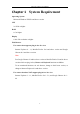
Network Camera User Manual Chapter 1 System Requirement Operating System Microsoft Windows XP SP1 and above version CPU 2.0 GHz or higher RAM 1G or higher Display 1024×768 resolution or higher Web Browser For camera that supports plug-in free live view Internet Explorer 8 – 11, Mozilla Firefox 30.0 and above version and Google Chrome 41.0 and above version.
Network Camera User Manual Chapter 2 Network Connection Note: You shall acknowledge that the use of the product with Internet access might be under network security risks. For avoidance of any network attacks and information leakage, please strengthen your own protection. If the product does not work properly, please contact with your dealer or the nearest service center. To ensure the network security of the network camera, we recommend you to have the network camera assessed and maintained termly.
Network Camera User Manual computer with a network cable as shown in Figure 2-1. Refer to the Figure 2-2 to set network camera over the LAN via a switch or a router. or Network Cable Network Camera 半球 Computer Figure 2-1 Connecting Directly or or tw Ne Ne tw le ab kC 网络交换机 ork C abl e or Network Camera 半球 Computer Figure 2-2 Connecting via a Switch or a Router 2.1.
Network Camera User Manual to search the IP address. Figure 2-3 Activation via Web Browser 3. Create and input a password into the password field. A password with user name in it is not allowed. STRONG PASSWORD RECOMMENDED–We highly recommend you create a strong password of your own choosing (using a minimum of 8 characters, including at least three of the following categories: upper case letters, lower case letters, numbers, and special characters) in order to increase the security of your product.
Network Camera User Manual 2. Check the device status from the device list, and select the inactive device. Select inactive device. Input and confirm password. Figure 2-4 SADP Interface Note: The SADP software supports activating the camera in batch. Refer to the user manual of SADP software for details. 3. Create and input the password in the password field, and confirm the password. A password with user name in it is not allowed.
Network Camera User Manual failed, please make sure that the password meets the requirement and try again. 5. Change the device IP address to the same subnet with your computer by either modifying the IP address manually or checking the checkbox of Enable DHCP. Figure 2-5 Modify the IP Address 6. Input the admin password and click Modify to activate your IP address modification. The batch IP address modification is supported by the SADP. Refer to the user manual of SADP for details.
Network Camera User Manual the figure below. Figure 2-6 Control Panel 2. Click the Device Management icon to enter the Device Management interface, as shown in the figure below.
Network Camera User Manual Figure 2-7 Device Management Interface 3. Check the device status from the device list, and select an inactive device. 4. Click the Activate button to pop up the Activation interface. 5. Create a password and input the password in the password field, and confirm the password. A password with user name in it is not allowed.
Network Camera User Manual Figure 2-8 Activation Interface (Client Software) 6. Click OK button to start activation. 7. Click the Modify Netinfo button to pop up the Network Parameter Modification interface, as shown in the figure below. Figure 2-9 Modifying the Network Parameters 8. Change the device IP address to the same subnet with your computer by either modifying the IP address manually or checking the checkbox of Enable DHCP. 9. Input the password to activate your IP address modification.
Network Camera User Manual 2.1.3 (Optional) Setting Security Question Security question is used to reset the admin password when admin user forgets the password. Admin user can follow the pop-up window to complete security question settings during camera activation. Or, admin user can go to User Management interface to set up the function. 2.2 Setting the Network Camera over the WAN Purpose: This section explains how to connect the network camera to the WAN with a static IP or a dynamic IP.
Network Camera User Manual 5. Visit the network camera through a web browser or the client software over the internet. Figure 2-10 Accessing the Camera through Router with Static IP Connecting the network camera with static IP directly You can also save the static IP in the camera and directly connect it to the internet without using a router. Refer to Section 2.1.2 for detailed IP address configuration of the network camera. Figure 2-11 Accessing the Camera with Static IP Directly 2.2.
Network Camera User Manual with port mapping. Note: Refer to Appendix 2 for detailed information about port mapping. 5. Apply a domain name from a domain name provider. 6. Configure the DDNS settings in the setting interface of the router. 7. Visit the camera via the applied domain name. Connecting the network camera via a modem Purpose: This camera supports the PPPoE auto dial-up function. The camera gets a public IP address by ADSL dial-up after the camera is connected to a modem.
Network Camera User Manual 1. Apply a domain name from a domain name provider. 2. Configure the DDNS settings in the DDNS Settings interface of the network camera. Refer to Section 7.1.2 Configuring DDNS Settings for detailed configuration. 3. Visit the camera via the applied domain name.
Network Camera User Manual Chapter 3 Access to the Network Camera 3.1 Accessing by Web Browsers Note: For certain camera models, HTTPS is enabled by default and the camera creates an unsigned certificate automatically. When you access to the camera the first time, the web browser prompts a notification about the certificate issue. To cancel the notification, install a signed-certificate to the camera. For detailed operation, see 7.2.5 HTTPS Settings. Steps: 1. Open the web browser. 2.
Network Camera User Manual 4. Click Login. 5. (Optional) Install the plug-in before viewing the live video and operating the camera. Follow the installation prompts to install the plug-in Note: For camera that supports plug-in free live view, if you are using Google Chrome 45 and its above version or Mozilla Firefox 52 and its above version, plug-in installation is not required. But Picture and Playback functions are hidden.
Network Camera User Manual Figure 3-2 iVMS-4200 Control Panel Figure 3-3 iVMS-4200 Main View 24
Network Camera User Manual Chapter 4 Wi-Fi Settings Purpose: By connecting to the wireless network, you don’t need to use cable of any kind for network connection, which is very convenient for the actual surveillance application. Note: This chapter is only applicable for the cameras with the built-in Wi-Fi module. Configuring Wi-Fi Connection in Manage and Ad-hoc Modes Purpose: Two connection modes are supported. Choose a mode as desired and perform the steps to configure the Wi-Fi.
Network Camera User Manual 3. Click to choose a wireless connection on the list. Wi-Fi Setting- Manage Mode 4. Check the radio button to select the Network mode as Manage, and the Security mode of the network is automatically shown when you select the wireless network, please don’t change it manually. Note: These parameters are exactly identical with those of the router. 5. Enter the key to connect the wireless network. The key should be that of the wireless network connection you set on the router.
Network Camera User Manual 2. Customize a SSID for the camera. 3. Choose the Security Mode of the wireless connection. 4. Enable the wireless connection function for your PC. 5. On the PC side, search the network and you can see the SSID of the camera listed. Ad-hoc Connection Point 6. Choose the SSID and connect. Security Mode Description: Security Mode You can choose the Security Mode as not-encrypted, WEP, WPA-personal, WPA-enterprise, WPA2-personal, and WPA2-enterprise.
Network Camera User Manual WEP Mode Authentication - Select Open or Shared Key System Authentication, depending on the method used by your access point. Not all access points have this option, in which case they probably use Open System, which is sometimes known as SSID Authentication. Key length - This sets the length of the key used for the wireless encryption, 64 or 128 bit. The encryption key length can sometimes be shown as 40/64 and 104/128.
Network Camera User Manual Choose the type of client/server authentication being used by the access point; EAP-TLS or EAP-PEAP. EAP-TLS EAP-TLS Identity - Enter the user ID to present to the network. Private key password – Enter the password for your user ID. EAPOL version - Select the version used (1 or 2) in your access point. CA Certificates - Upload a CA certificate to present to the access point for authentication.
Network Camera User Manual strongly recommend the use of strong passwords for all functions and network devices. The password should be something of your own choosing (using a minimum of 8 characters, including at least three of the following categories: upper case letters, lower case letters, numbers and special characters) in order to increase the security of your product. Proper configuration of all passwords and other security settings is the responsibility of the installer and/or end-user.
Network Camera User Manual PBC Mode: PBC refers to the Push-Button-Configuration, in which the user simply has to push a button, either an actual or virtual one (as the button on the configuration interface of the IE browser), on both the Access Point (and a registrar of the network) and the new wireless client device. 1. Check the checkbox of to enable WPS. 2. Choose the connection mode as PBC. Note: Support of this mode is mandatory for both the Access Points and the connecting devices. 3.
Network Camera User Manual Use PIN Code If the PIN code is generated from the router side, you should enter the PIN code you get from the router side in the Router PIN code field. 3. Click Connect. Or You can generate the PIN code on the camera side. And the expired time for the PIN code is 120 seconds. 1. Click Generate. 2. Enter the code to the router, in the example, enter 48167581 to the router.
Network Camera User Manual Setting WLAN Parameters 3. Customize the IPv4 address, the IPv4 Subnet Mask and the Default Gateway. The setting procedure is the same with that of LAN. If you want to be assigned the IP address you can check the checkbox to enable the DHCP.
Network Camera User Manual Chapter 5 Live View 5.1 Live View Page Purpose: The live view page allows you to view the real-time video, capture images, realize PTZ control, set/call presets and configure video parameters. Log in the network camera to enter the live view page, or you can click Live View on the menu bar of the main page to enter the live view page.
Network Camera User Manual For IE (Internet Explorer) users, plug-ins as webcomponents and quick time are selectable. And for Non-IE users, webcomponents, quick time, VLC or MJPEG are selectable if they are supported by the web browser. Note: For camera that supports plug-in free live view, when Google Chrome 45 and its above version or Mozilla Firefox 52 and its above version are used, plug-in installation is not required. But Picture and Playback functions are hidden.
Network Camera User Manual Icon Description Manually capture the picture. / Manually start/stop recording. / Audio on and adjust volume /Mute. / Turn on/off microphone. / Start/stop digital zoom function. / Start/stop pixel counter Note: The icons vary according to the different camera models. Pixel Counter: 1. Click Start Pixel Counter button to enable the function. 2. Drag the mouse on the image to select the desired rectangle area.
Network Camera User Manual panel. Click to hide it. 2. Specify PTZ, Display, OSD and Video/Audio and VCA resource parameters. For more settings, go to Configuration > Image and Configuration > Video/Audio. Display Settings Scene: Select a scene according to actual installation environment. (Only certain camera models support.) WDR: The WDR (Wide Dynamic Range) function helps the camera provide clear images even under back light circumstances.
Network Camera User Manual 5.5 Operating PTZ Control Purpose: In the live view interface, you can use the PTZ control buttons to realize pan/tilt/zoom control of the camera. Note: To realize PTZ control, the camera connected to the network must support the PTZ function or have a pan/tilt unit installed to the camera. Please properly set the PTZ parameters on RS485 settings page referring to Section 6.2.4 RS485 Settings. 5.5.
Network Camera User Manual Zoom in/out Focus near/far Iris +/PTZ speed adjustment Light on/off Wiper on/off Auxiliary focus Initialize lens Adjust speed of pan/tilt movements Start Manual Tracking Start 3D Zoom 5.5.2 Setting/Calling a Preset Setting a Preset: 3. In the PTZ control panel, select a preset number from the preset list. Figure 5-4 Setting a Preset 4. Use the PTZ control buttons to move the lens to the desired position. • Pan the camera to the right or left. • Tilt the camera up or down.
Network Camera User Manual Calling a Preset: This feature enables the camera to point to a specified preset scene manually or when an event takes place. For the defined preset, you can call it at any time to the desired preset scene. In the PTZ control panel, select a defined preset from the list and click to call the preset. Or you can place the mouse on the presets interface, and call the preset by typing the preset No. to call the corresponding presets. Figure 5-5 Calling a Preset 5.5.
Network Camera User Manual Figure 5-6 Add Patrol Path 6. Click OK to save a patrol. 7. Click to start the patrol, and click 8. (Optional) Click to stop it. to delete a patrol.
Network Camera User Manual Chapter 6 Network Camera Configuration 6.1 Configuring Local Parameters Purpose: The local configuration refers to the parameters of the live view, record files and captured pictures. The record files and captured pictures are the ones you record and capture using the web browser and thus the saving paths of them are on the PC running the browser. Steps: 1. Enter the Local Configuration interface: Configuration > Local. 2.
Network Camera User Manual Display POS Information: Enable the function, feature information of the detected target is dynamically displayed near the target in the live image. The feature information of different functions are different. For example, ID and waiting time for Queue Management, height for People Counting, etc. Note: Display POS Information is only available for certain camera models. Image Format: Choose the image format for picture capture.
Network Camera User Manual 3. Click Save to save the settings. 6.2 Configure System Settings Purpose: Follow the instructions below to configure the system settings, include System Settings, Maintenance, Security, and User Management, etc. 6.2.1 Configuring Basic Information Enter the Device Information interface: Configuration > System > System Settings > Basic Information. In the Basic Information interface, you can edit the Device Name and Device No.
Network Camera User Manual Time Settings 2. Select the Time Zone of your location from the drop-down menu. 3. Configure the NTP settings. (1) Click to enable the NTP function. (2) Configure the following settings: Server Address: IP address of NTP server. NTP Port: Port of NTP server. Interval: The time interval between the two synchronizing actions with NTP server. (3) (Optional) You can click the Test button to test the time synchronization function via NTP server.
Network Camera User Manual Note: If the camera is connected to a public network, you should use a NTP server that has a time synchronization function, such as the server at the National Time Center (IP Address: 210.72.145.44). If the camera is set in a customized network, NTP software can be used to establish a NTP server for time synchronization. Configure the manual time synchronization. (1) Check the Manual Time Sync. item to enable the manual time synchronization function.
Network Camera User Manual 1. Enter RS232 Port Setting interface: Configuration > System > System Settings > RS232. 2. Configure the Baud Rate, Data Bit, Stop Bit, Parity, Flow Control, and Usage. Figure 6-5 RS232 Settings Note: If you want to connect the camera by the RS232 port, the parameters of the RS232 should be exactly the same with the parameters you configured here. 3. Click Save to save the settings. 6.2.
Network Camera User Manual Figure 6-6 RS-485 Settings Set the RS485 parameters and click Save to save the settings. 2. By default, the Baud Rate is set as 9600 bps, the Data Bit is 8, the stop bit is 1 and the Parity and Flow Control is None. Note: The Baud Rate, PTZ Protocol and PTZ Address parameters should be exactly the same as the PTZ camera parameters. 6.2.
Network Camera User Manual Figure 6-7 DST Settings 2. Select the start time and the end time. 3. Select the DST Bias. 4. Click Save to activate the settings. 6.2.6 Configuring External Devices Purpose: For the device supported external devices, including the wiper on the housing or the LED light, you can control them via the Web browser. External devices vary according to the different camera models. Steps: 1. Enter the External Device configuration interface.
Network Camera User Manual the Start Time and End Time. Figure 6-9 Set Schedule Auto: The LED will be turned on according to the environment illumination. 5. Click Save to save the settings. 6.2.7 Open Source Software License Information about the open source software that applies to the IP camera can be checked if required. Go to Configuration > System Settings > About. 6.
Network Camera User Manual • For camera that supports Wi-Fi, wireless dial, or wlan function, Restore action does not restore the related settings of mentioned functions to default. Information Export Device Parameters: click to export the current configuration file of the camera. This operation requires admin password to proceed. For the exported file, you also have to create an encryption password. The encryption password is required when you import the file to other cameras.
Network Camera User Manual The operation, alarm, exception and information of the camera can be stored in log files. You can also export the log files on your demand. Before you start: Please configure network storage for the camera or insert a SD card in the camera. Steps: 1. Enter log searching interface: Configuration > System > Maintenance > Log. Figure 6-10 Log Searching Interface 2. Set the log search conditions to specify the search, including the Major Type, Minor Type, Start Time and End Time.
Network Camera User Manual 4. To export the log files, click Export to save the log files. 6.3.3 System Service Purpose: System service settings refer to the hardware service the camera supports. Supported functions vary according to the different cameras. For the cameras support IR Light, ABF (Auto Back Focus), Auto Defog, or Status LED, you can select to enable or disable the corresponding service according to the actual demands.
Network Camera User Manual Figure 6-12 Authentication 2. Set up authentication method for RTSP authentication and WEB authentication. Caution: Digest is the recommended authentication method for better data security. You must be aware of the risk if you adopt basic as the authentication method. 3. Click Save to save the settings. 6.4.2 IP Address Filter Purpose: This function makes it possible for access control. Steps: 1.
Network Camera User Manual Figure 6-14 Add an IP (3) Click the OK to finish adding. Modify an IP Address Steps: (1) Left-click an IP address from filter list and click Modify. (2) Modify the IP address in the text filed. Figure 6-15 Modify an IP (3) Click the OK to finish modifying. Delete an IP Address or IP Addresses. Select the IP address(es) and click Delete. 5. Click Save to save the settings. 6.4.
Network Camera User Manual Figure 6-16 Security Service 2. Check the checkbox of Enable Illegal Login Lock. Illegal Login Lock: it is used to limit the user login attempts. Login attempt from the IP address is rejected if admin user performs 7 failed user name/password attempts (5 times for the operator/user). Note: If the IP address is rejected, you can try to login the device after 30 minutes. 6.
Network Camera User Manual The admin user cannot be deleted and you can only change the admin password. Steps: 1. Click Add to add a user. 2. Input the Admin Password, User Name, select Level and input Password. Notes: ● Up to 31 user accounts can be created. ● Users of different levels own different default permissions. Operator and user are selectable.
Network Camera User Manual 4. Click OK to finish the user modification. Deleting a User Steps: 1. Click to select the user you want to delete and click Delete. 2. Click OK on the pop-up dialogue box to confirm the deletion. Setting Simultaneous Login Steps: 1. Click General. 2. Slide the slide bar to set the simultaneous login. If the number of the illegal login attempts exceeds the set threshold, your access will be denied. As Operator or User Operator or user can modify password.
Network Camera User Manual Chapter 7 Network Settings Purpose: Follow the instructions in this chapter to configure the basic settings and advanced settings. 7.1 Configuring Basic Settings Purpose: You can configure the parameters, including TCP/IP, DDNS, PPPoE, Port, and NAT, etc., by following the instructions in this section. 7.1.1 Configuring TCP/IP Settings Purpose: TCP/IP settings must be properly configured before you operate the camera over network. The camera supports both the IPv4 and IPv6.
Network Camera User Manual TCP/IP Settings 2. Configure the basic network settings, including the NIC Type, IPv4 or IPv6 Address, IPv4 or IPv6 Subnet Mask, IPv4 or IPv6 Default Gateway, MTU settings and Multicast Address. 3. (Optional) Check the checkbox of Enable Multicast Discovery, and then the online network camera can be automatically detected by client software via private multicast protocol in the LAN. 4. Configure the DNS server. Input the preferred DNS server, and alternate DNS server. 5.
Network Camera User Manual multicast group address. Before utilizing this function, you have to enable the Multicast function of your router. A reboot is required for the settings to take effect. 7.1.2 Configuring DDNS Settings Purpose: If your camera is set to use PPPoE as its default network connection, you can use the Dynamic DNS (DDNS) for network access. Before you start: Registration on the DDNS server is required before configuring the DDNS settings of the camera. Steps: 1.
Network Camera User Manual Figure 7-2 DynDNS Settings NO-IP: Steps: (1) Choose the DDNS Type as NO-IP. Figure 7-3 NO-IP DNS Settings (2) Enter the Server Address as www.noip.com (3) Enter the Domain name you registered. (4) Enter the User Name and Password. (5) Click Save and then you can view the camera with the domain name. Note: Reboot the device to make the settings take effect.
Network Camera User Manual 7.1.3 Configuring PPPoE Settings Steps: 1. Enter the PPPoE Settings interface: Configuration > Network > Basic Settings > PPPoE PPPoE Settings 2. Check the Enable PPPoE checkbox to enable this feature. 3. Enter User Name, Password, and Confirm password for PPPoE access. Note: The User Name and Password should be assigned by your ISP.
Network Camera User Manual You can set the port No. of the camera, e.g., HTTP port, RTSP port and HTTPS port. Steps: 1. Enter the Port Settings interface, Configuration > Network > Basic Settings > Port Port Settings 2. Set the ports of the camera. HTTP Port: The default port number is 80, and it can be changed to any port No. which is not occupied. RTSP Port: The default port number is 554 and it can be changed to any port No. ranges from 1 to 65535.
Network Camera User Manual Note: WebSocket and WebSockets protocol are used for plug-in free live view. For detailed information, see 7.2.9. 3. Click Save to save the settings. Note: A reboot is required for the settings to take effect. 7.1.5 Configure NAT (Network Address Translation) Settings Purpose: NAT interface allows you to configure the UPnP™ parameters.
Network Camera User Manual 3. Choose a friendly name for the camera, or you can use the default name. 4. Select the port mapping mode. Manual and Auto are selectable. Note: If you select Auto, you should enable UPnP™ function on the router. If you select Manual, you can customize the value of the external port and complete port mapping settings on router manually. 5. Click Save to save the settings. 7.
Network Camera User Manual strongly recommend the use of strong passwords for all functions and network devices. The password should be something of your own choosing (using a minimum of 8 characters, including at least three of the following categories: upper case letters, lower case letters, numbers and special characters) in order to increase the security of your product. Proper configuration of all passwords and other security settings is the responsibility of the installer and/or end-user.
Network Camera User Manual SNMP Settings 2. Check the checkbox of Enable SNMPv1, Enable SNMP v2c, Enable SNMPv3 to enable the feature correspondingly. 3. Configure the SNMP settings.
Network Camera User Manual configure here. 4. Click Save to save and finish the settings. Notes: • A reboot is required for the settings to take effect. • To lower the risk of information leakage, you are suggested to enable SNMP v3 instead of SNMP v1 or v2. 7.2.2 Configuring FTP Settings Purpose: You can configure the FTP server related information to enable the uploading of the captured pictures to the FTP server. The captured pictures can be triggered by events or a timing snapshot task. Steps: 1.
Network Camera User Manual FTP server login. For your privacy and to better protect your system against security risks, we strongly recommend the use of strong passwords for all functions and network devices. The password should be something of your own choosing (using a minimum of 8 characters, including at least three of the following categories: upper case letters, lower case letters, numbers and special characters) in order to increase the security of your product.
Network Camera User Manual anonymous access to the FTP server. Note: The anonymous access function must be supported by the FTP server. 6. Click Save to save the settings. 7.2.3 Configuring Email Settings Purpose: The system can be configured to send an Email notification to all designated receivers if an alarm event is detected, e.g., motion detection event, video loss, video tampering, etc.
Network Camera User Manual The SMTP port should be set as 465 for this encryption method. When you select SSL or TLS and enable STARTTLS, emails will be sent after encrypted by STARTTLS, and the SMTP port should be set as 25. Note: If you want to use STARTTLS, make sure that the protocol is supported by your e-mail server. If you check the Enable STARTTLS checkbox when the protocol is not supported by your e-mail sever, your e-mail will not be encrypted.
Network Camera User Manual Email Settings 4. Click Save to save the settings. 7.2.4 Platform Access Purpose: Platform access provides you an option to manage the devices via platform. Steps: 1. Enter the Platform Access settings interface: Configuration > Network > Advanced Settings > Platform Access 2. Check the checkbox of Enable to enable the platform access function of the device. 3. Select the Platform Access Mode. Note: Hik-Connect is an application for mobile devices.
Network Camera User Manual If you select Platform Access Mode as Hik-Connect, 1) Click and read "Terms of Service" and "Privacy Policy" in pop-up window. 2) Create a verification code or change the verification code for the camera. Note: • The verification code is required when you add the camera to Hik-Connect app. • For more information about the Hik-Connect app, refer to Hik-Connect Mobile Client User Manual. 4. You can use the default server address.
Network Camera User Manual Figure 7-10 HTTPS Configuration Interface 4. Create the self-signed certificate or authorized certificate. Create Self-signed Certificate Create the self-signed certificate (1) Select Create Self-signed Certificate as the Installation Method. (2) Click Create button to enter the creation interface. (3) Enter the country, host name/IP, validity and other information. (4) Click OK to save the settings.
Network Camera User Manual Click Browse and Install to import the certificate to the device. Import the Certificate (1) b) Select Create the certificate request first and continue the installation. Click Browse and Install to import the certificate to the device. Import the Certificate (2) 5. There will be the certificate information after your successfully creating and installing the certificate. Installed Certificate 6.
Network Camera User Manual Note: The exported certificate should be saved in the certificate folder of your client software before adding the device to your PC client. 7. Click the Save button to save the settings. 7.2.6 Configuring QoS Settings Purpose: QoS (Quality of Service) can help solve the network delay and network congestion by configuring the priority of data sending. Steps: 1. Enter the QoS Settings interface: Configuration > Network > Advanced Settings > QoS QoS Settings 2.
Network Camera User Manual 7.2.7 Configuring 802.1X Settings Purpose: The IEEE 802.1X standard is supported by the network cameras, and when the feature is enabled, the camera data is secured and user authentication is needed when connecting the camera to the network protected by the IEEE 802.1X. Before you start: The authentication server must be configured. Please apply and register a user name and password for 802.1X in the server.
Network Camera User Manual 802.1X Settings 2. Check the Enable IEEE 802.1X checkbox to enable the feature. 3. Configure the 802.1X settings, including Protocol, EAPOL version, User Name, Password and Confirm. Note: The EAPOL version must be identical with that of the router or the switch. 4. Enter the user name and password to access the server. 5. Click Save to finish the settings. Note: A reboot is required for the settings to take effect. 7.2.
Network Camera User Manual 7.2.9 Network Service You can control the ON/OFF status of certain protocol that the camera supports. Note: • Keep unused function OFF for security concern. • Supported function varies according to camera models. WebSocket and WebSockets WebSocket or WebSockets protocol should be enabled if you use Google Chrome 45 and its above version or Mozilla Firefox 52 and its above version to visit your camera.
Network Camera User Manual Before you start: The destination IP or host name should support the HTTP protocol to receive the alarm information. Steps: 1. Enter the HTTP Listening interface, Configuration > Network > Advanced Settings > Listening. Figure 7-17 HTTP Listening 2. Enter the desired destination IP or host name, URL and port. 3. You can click Test to test whether the entered IP address or host name are valid. 4. Or you can click Default to reset the destination IP or host name.
Network Camera User Manual Chapter 8 Video/Audio Settings Purpose: Follow the instructions below to configure the video setting, audio settings, ROI, Display info. on Stream, etc. 8.1 Configuring Video Settings For certain camera models, you can configure parameters for available video streams, for example, the main stream, the sub-stream, etc. Steps: 1. Enter the Video Settings interface, Configuration > Video/Audio > Video Video Settings 2. Select the Stream Type.
Network Camera User Manual • The main stream is usually for recording and live view with good bandwidth, and the sub-stream can be used for live view when the bandwidth is limited. 3. You can customize the following parameters for the selected stream type. Video Type: Select the stream type to video stream, or video & audio composite stream. The audio signal will be recorded only when the Video Type is Video & Audio. Resolution: Select the resolution of the video output.
Network Camera User Manual H.264+ and H.265+: • H.264+: If you set the main stream as the stream type, and H.264 as the video encoding, you can see H.264+ available. H.264+ is an improved compression coding technology based on H.264. By enabling H.264+, users can estimate the HDD consumption by its maximum average bitrate. Compared to H.264, H.264+ reduces storage by up to 50% with the same maximum bitrate in most scenes. • H.265+: If you set the main stream as the stream type, and H.
Network Camera User Manual maximum average bitrate manually from 32 Kbps to the value of the set maximum bitrate. Profile: When you select H.264 or H.265 as video encoding, you can set the profile. Selectable profiles vary according to camera models. I Frame Interval: Set I Frame Interval from 1 to 400. SVC: Scalable Video Coding is an extension of the H.264/AVC and H.265 standard. Select OFF/ON to disable/enable the SVC function.
Network Camera User Manual Audio Settings 2. Configure the following settings. Note: Audio settings vary according to different camera models. Audio Encoding: G.722.1, G.711 ulaw, G.711alaw, G.726, MP2L2 and PCM are selectable. For MP2L2, the Sampling Rate and Audio Stream Bitrate are configurable. For PCM, the Sampling Rate can be set. Audio Input: MicIn and LineIn are selectable for the connected microphone and pickup respectively. Input Volume: 0-100 adjustable.
Network Camera User Manual Region of Interest Settings Steps: 1. Enter the ROI settings interface: Configuration > Video/Audio > ROI. 2. Select the Stream Type for ROI encoding. 3. Check the checkbox of Enable under Fixed Region item. 4. Set Fixed Region for ROI. (1) Select the Region No. from the drop-down list. (2) Check the Enable checkbox to enable ROI function for the chosen region.
Network Camera User Manual (3) Click Drawing. Click and drag the mouse on the view screen to draw a red rectangle as the ROI region. You can click Clear to cancel former drawing. Click Stop Drawing when you finish. (4) Select the ROI level. (5) Enter a region name for the chosen region. (6) Click Save the save the settings of ROI settings for chosen fixed region. (7) Repeat steps (1) to (6) to setup other fixed regions. 5. Set Dynamic Region for ROI. (1) Check the checkbox to enable Face Tracking.
Network Camera User Manual Chapter 9 Image Settings Purpose: Follow the instructions in this chapter to configure the image parameters, including display settings, OSD settings, privacy mask, and picture overlay. 9.1 Configuring Display Settings Purpose: Configure the image adjustment, exposure settings, day/night switch, backlight settings, white balance, image enhancement, video adjustment, and other parameters in display settings.
Network Camera User Manual Image Adjustment Brightness describes bright of the image, which ranges from 1 to 100. Contrast describes the contrast of the image, which ranges from 1 to 100. Saturation describes the colorfulness of the image color, which ranges from 1 to 100. Sharpness describes the edge contrast of the image, which ranges from 1 to 100. Exposure Settings If the camera is equipped with the fixed lens, only Manual is selectable, and the iris mode is not configurable.
Network Camera User Manual Day/Night Switch Select the Day/Night Switch mode according to different surveillance demand. Day, Night, Auto, Scheduled-Switch, and Triggered by alarm input are selectable for day/night switch. Day/Night Switch Day: the camera stays at day mode. Night: the camera stays at night mode. Auto: the camera switches between the day mode and the night mode according to the illumination automatically.
Network Camera User Manual BLC Area: If you focus on an object against strong backlight, the object will be too dark to be seen clearly. BLC compensates light to the object in the front to make it clear. OFF, Up, Down, Left, Right, Center, Auto, and Custom are selectable. Note: If BLC mode is set as Custom, you can draw a red rectangle on the live view image as the BLC area. WDR: Wide Dynamic Range can be used when there is a high contrast of the bright area and the dark area of the scene.
Network Camera User Manual video. Grey Scale: You can choose the range of the grey scale as [0-255] or [16-235]. Video Adjustment Mirror: It mirrors the image so you can see it inversed. Left/Right, Up/Down, Center, and OFF are selectable. Rotate: To make a complete use of the 16:9 aspect ratio, you can enable the rotate function when you use the camera in a narrow view scene.
Network Camera User Manual OSD Settings Steps: 1. Enter the OSD Settings interface: Configuration > Image > OSD Settings. 2. Check the corresponding checkbox to select the display of camera name, date or week if required. 3. Edit the camera name in the text field of Camera Name. 4. Select from the drop-down list to set the time format and date format. 5. Select from the drop-down list to set the time format, date format, display mode, OSD size and OSD color. 6. Configure the text overlay settings.
Network Camera User Manual 8. Click Save to save the settings. 9.3 Configuring Privacy Mask Purpose: Privacy mask enables you to cover certain areas on the live video to prevent certain spots in the surveillance area from being live viewed and recorded. Steps: 1. Enter the Privacy Mask Settings interface: Configuration > Image > Privacy Mask. 2. Check the checkbox of Enable Privacy Mask to enable this function. 3. Click Draw Area. Privacy Mask Settings 4.
Network Camera User Manual you set without saving them. 6. Click Save to save the settings. 9.4 Configuring Picture Overlay Purpose: Picture overlay enables you to overlay a picture on the image. This function enables a certain enterprise or users to overlay their logo on the image. Steps: 1. Enter the Picture Overlay Settings interface, Configuration > Image > Picture Overlay. Picture Overlay 2. Click Browse to select a picture. 3. Click Upload to upload it. 4.
Network Camera User Manual Configuring Image Parameters Switch Purpose: Image parameters scheduled-switch configuration interface enables you to set the time period and linked scene and it will go to the linked scene in the configured time period when you check the corresponding checkbox. Scheduled-Switch Configuration Interface Steps: 1. Enter Image Parameters Switch interface, Configuration > Image > Image Parameters Switch. 2. Check Scheduled-Switch. 3. Set the time period and the linked scene.
Network Camera User Manual Chapter 10 Event Settings This section explains how to configure the network camera to respond to alarm events, including basic event and smart event. 10.1 Basic Events You can configure the basic events by following the instructions in this section, including motion detection, video tampering, alarm input, alarm output, and exception, etc. These events can trigger the linkage methods, such as Notify Surveillance Center, Send Email, Trigger Alarm Output, etc.
Network Camera User Manual 3. Check the checkbox of Enable Dynamic Analysis for Motion if you want to mark the detected objects with green rectangles. Note: Select Disable for rules if you don’t want the detected objected displayed with the green rectangles. Select disable rules from Configuration > Local Configuration > Live View Parameters-rules. Enable Motion Detection 4. Click Draw Area. Click and drag the mouse on the live video to draw a motion detection area.
Network Camera User Manual Task 2: Set the Arming Schedule for Motion Detection Arming Schedule Steps: 1. Click Arming Schedule to edit the arming schedule. 2. Click on the time bar and drag the mouse to select the time period. Figure 10-3 Arming Schedule Note: Click on the selected time period, you can adjust the time period to the desired time by either moving the time bar or input the exact time period. 3.
Network Camera User Manual save the settings. 4. Move the mouse to the end of each day, a copy dialogue box pops up, and you can copy the current settings to other days. 5. Click Save to save the settings. Note: The time of each period can’t be overlapped. Up to 8 periods can be configured for each day. Task 3: Set the Linkage Method for Motion Detection Check the checkbox to select the linkage method.
Network Camera User Manual complete Email setup in advance. Upload to FTP/Memory Card/NAS Capture the image when an alarm is triggered and upload the picture to a FTP server. Notes: ● Set the FTP address and the remote FTP server first. Refer to Section 7.2.2 Configuring FTP Settings for detailed information. ● Go to Configuration > Storage > Schedule Settings> Capture > Capture Parameters page, enable the event-triggered snapshot, and set the capture interval and capture number.
Network Camera User Manual Expert Mode of Motion Detection Day/Night Switch OFF Steps: 1. Draw the detection area as in the normal configuration mode. Up to 8 areas are supported. 2. Select OFF for Switch Day and Night Settings. 3. Select the area by clicking the area No. 4. Slide the cursor to adjust the sensitivity and proportion of object on the area for the selected area. 5. Set the arming schedule and linkage method as in the normal configuration mode. 6. Click Save to save the settings.
Network Camera User Manual 6. Set the arming schedule and linkage method as in the normal configuration mode. 7. Click Save to save the settings. Day/Night Scheduled-Switch Steps: 1. Draw the detection area as in the normal configuration mode. Up to 8 areas are supported. 2. Select Scheduled-Switch for Switch Day and Night Settings. Day/Night Scheduled-Switch 3. Select the start time and the end time for the switch timing. 4. Select the area by clicking the area No.. 5.
Network Camera User Manual 2. Check Enable Video Tampering checkbox to enable the video tampering detection. 3. Click Edit to edit the arming schedule for video tampering. The arming schedule configuration is the same as the setting of the arming schedule for motion detection. Refer to Task 2: Set the Arming Schedule for Motion Detection in Section 10.1.1. 4. Check the checkbox to select the linkage method taken for the video tampering.
Network Camera User Manual Alarm Input Settings 3. Click Arming Schedule to set the arming schedule for the alarm input. Refer to Task 2: Set the Arming Schedule for Motion Detection in Section 10.1.1. 4. Click Linkage Method and check the checkbox to select the linkage method taken for the alarm input. Refer to Task 3: Set the Linkage Method for Motion Detection in Section 10.1.1. 5. You can copy your settings to other alarm inputs. 6. Click Save to save the settings.
Network Camera User Manual 10.1.4 Configuring Alarm Output Alarm Output Settings Steps: 1. Enter the Alarm Output Settings interface: Configuration> Event > Basic Event > Alarm Output. 2. Select one alarm output channel in the Alarm Output drop-down list. You can also set a name for the alarm output (optional). 3. The Delay time can be set to 5sec, 10sec, 30sec, 1min, 2min, 5min, 10min or Manual. The delay time refers to the time duration that the alarm output remains in effect after alarm occurs. 4.
Network Camera User Manual 6. Click Save to save the settings. 10.1.5 Handling Exception The exception type can be HDD full, HDD error, network disconnected, IP address conflicted and illegal login to the cameras. Steps: 1. Enter the Exception Settings interface: Configuration > Event > Basic Event > Exception. 2. Check the checkbox to set the actions taken for the Exception alarm. Refer to Task 3: Set the Linkage Method for Motion Detection in Section 10.1.1. 3. Click Save to save the settings. 10.
Network Camera User Manual Smart Event > Audio Exception Detection. Figure 10-9 Audio Exception Detection 2. Check the checkbox of Audio Loss Exception to enable the audio loss detection function. 3. Check the checkbox of Sudden Increase of Sound Intensity Detection to detect the sound steep rise in the surveillance scene. You can set the detection sensitivity and threshold for sound steep rise. 4.
Network Camera User Manual 6. Click Linkage Method and select the linkage methods for audio exception, including Notify Surveillance Center, Send Email, Upload to FTP/Memory Card/NAS, Trigger Channel for recording and Trigger Alarm Output. 7. Click Save to save the settings. Configuring Defocus Detection Purpose: The image blur caused by defocus of the lens can be detected, and some certain actions can be taken when the alarm is triggered.
Network Camera User Manual Scene change detection function detects the change of surveillance environment affected by the external factors, such as the intentional rotation of the camera. Some certain actions can be taken when the alarm is triggered. Note: Scene change detection function varies according to different camera models. Steps: 1. Enter the Scene Change Detection settings interface, Configuration > Event > Smart Event > Scene Change Detection. Figure 10-11 Scene Change Detection 2.
Network Camera User Manual Chapter 11 People Counting Purpose: People function is used to calculate the number of object entered or exited a certain configured area and it is widely applied to the entrances or exits. Before you start: The camera is recommended to be installed right above the entrance/exit, and make sure it is installed properly. Refer to Quick Start Guide of Dual-Lens People Counting Camera for installation advice.
Network Camera User Manual Figure 11-1 People Counting Configuration 2. Check Enable People Counting checkbox to enable the function. 3. Select the calibration mode and then click Calibration. Auto calibration and manual calibration are selectable. Auto: The camera automatically calculates the lens height, tilt angle and heel angle. Select the calibration area and drag it to the level ground.
Network Camera User Manual detection area and starts people counting. 4. Click 5. Click on the left of the live view image to draw a detection region. on the left of the live view image to draw the detection line. The arrow stands for the direction of entering, you can click • to change the direction. If the target crosses the counting area along the entering direction and crosses the detection line, then it is counted as the entering number.
Network Camera User Manual stands for the direction of entering, you can click • to change the direction. If the target crosses the counting area along the entering direction and crosses the detection line, then it is counted as the entering number. • If the target crosses the counting area along the exiting direction and crosses the detection line, then it is counted as the exiting number. An Example of Detection Line and Entry/Exit Area Arming Schedule Steps: 1.
Network Camera User Manual desired time by either moving the time bar or input the exact time period. 3. (Optional) Click Delete to delete the current arming schedule, or click Save to save the settings. 4. Move the mouse to the end of each day, a copy dialogue box pops up, and you can copy the current settings to other days. 5. Click Save to save the settings. Note: The time of each period can’t be overlapped. Up to 8 periods can be configured for each day. Linkage Method 1.
Network Camera User Manual Figure 11-5 Reverse Counting Alarm 11.2 Set the Shield Region Set the shield region. Click click to draw a polygon shield region. You can to clear all the shield regions. 11.3 Set the Data Uploading For Non-Mobile Models Data uploading is about how and when the counting data can be sent to clients and users. You can upload people counting data to surveillance center and client software through SDK and HTTP (if configured).
Network Camera User Manual and report format to activate the function. Note: Go to Configuration > Network > Advanced Settings > Email to set up email. Figure 11-6 Data Uploading For Mobile Models Select a trigger counting mode. None, or trigger by alarm input. None: Camera keeps counting, unaffected by door status. When you select None, people counting data is sent to surveillance center and client software through SDK (default) and HTTP (if configured).
Network Camera User Manual RS485 3. (Optional) If data uploading by HTTP is required, set up the HTTP Data Transmission parameters. 11.4 Set the Overlay and Capture Display VCA info. on Stream The green frames will be displayed on the target if in a live view or playback. Display Target info. on Alarm Picture There will be a frame on the target on the uploaded alarm picture if the checkbox is checked. Display Rule info.
Network Camera User Manual Figure 11-7 Advanced Parameters Enable Height Filter: Enable the function and set a height value. Persons and objects shorter than the set value are not counted as a valid target. Enable Counting Children: Enable the function and set a height value to calculate the number of the children higher than the set value.
Network Camera User Manual It displays the vehicle door status. Click Refresh to update the status. Clear Storage Data To clear stored data on camera, you can click the Clear button. Always do the operation with caution. Deleted data cannot be restored. One-touch Export Click the button to export the camera configuration parameters. Maintenance Mode If the function is enabled, certain camera settings will be changed, such as the resolution, frame rate and bit rate.
Network Camera User Manual Chapter 12 Storage Settings Before you start: To configure record settings, please make sure that you have the network storage device or local storage device configured. 12.1 Configuring Record Schedule Purpose: There are two kinds of recording for the cameras: manual recording and scheduled recording. In this section, you can follow the instructions to configure the scheduled recording.
Network Camera User Manual Figure 12-2 Record Parameters Pre-record: The time you set to start recording before the scheduled time or the event. For example, if an alarm triggers recording at 10:00, and the pre-record time is set as 5 seconds, the camera starts to record at 9:59:55. The Pre-record time can be configured as No Pre-record, 5s, 10s, 15s, 20s, 25s, 30s or not limited. Post-record: The time you set to stop recording after the scheduled time or the event.
Network Camera User Manual please refer to the Task 1: Set the Motion Detection Area in the Section 10.1.1. Record Triggered by Alarm If you select Alarm, the video will be recorded when the alarm is triggered via the external alarm input channels. Besides configuring the recording schedule, you have to set the Alarm Type and check the checkbox of Trigger Channel in the Linkage Method of Alarm Input Settings interface. For detailed information, please refer to Section 10.1.3.
Network Camera User Manual 12.2 Configure Capture Schedule Purpose: You can configure the scheduled snapshot and event-triggered snapshot. The captured picture can be stored in the local storage or network storage. Steps: 1. Enter the Capture Settings interface: Configuration > Storage > Storage Settings > Capture. Figure 12-3 Capture Configuration 2. Go to Capture Schedule tab to configure the capture schedule by click-and-drag the mouse on the time bar.
Network Camera User Manual 4. Click Save to save the settings. 5. Go to Capture Parameters tab to configure the capture parameters. (1) Check the Enable Timing Snapshot checkbox to enable continuous snapshot. (2) Select the picture format, resolution, quality and capture interval. (3) Check the Enable Event-triggered Snapshot checkbox to enable event-triggered snapshot. (4) Select the picture format, resolution, quality, capture interval, and capture number. Figure 12-5 Set Capture Parameters 6.
Network Camera User Manual 12.3 Configuring Net HDD Before you start: The network disk should be available within the network and properly configured to store the recorded files, log files, pictures, etc. Steps: 1. Add Net HDD. (1) Enter the Net HDD settings interface, Configuration > Storage > Storage Management > Net HDD. Add Network Disk (2) Enter the IP address of the network disk, and enter the file path. (3) Select the mounting type. NFS and SMB/CIFS are selectable.
Network Camera User Manual responsibility of the installer and/or end-user. (4) Click Save to add the network disk. 2. Initialize the added network disk. (1) Enter the HDD Settings interface, Configuration > Storage > Storage Management > HDD Management, in which you can view the capacity, free space, status, type and property of the disk.
Network Camera User Manual Figure 12-9 Quota Settings Note: Up to 8 NAS disks can be connected to the camera.
Network Camera User Manual Chapter 13 Playback Purpose: This section explains how to view the remotely recorded video files stored in the network disks or SD cards. Steps: 1. Click Playback on the menu bar to enter playback interface. Figure 13-1 Playback Interface 2. Select the date and click Search. Figure 13-2 Search Video 3. Click to play the video files found on this date.
Network Camera User Manual The toolbar on the bottom of Playback interface can be used to control playing process.
Network Camera User Manual Chapter 14 Picture Click Picture to enter the picture searching interface. You can search, view, and download the pictures stored in the local storage or network storage. Notes: Make sure HDD, NAS or memory card are properly configured before you process the picture search. Make sure the capture schedule is configured. Go to Configuration > Storage > Schedule Settings > Capture to set the capture schedule. Figure 14-1 Picture Search Interface Steps: 1.
Network Camera User Manual Chapter 15 Application Click Application to enter the statistics counting interface. You can search, view, and download the counting data stored in the local storage or network storage. Note: Application function varies according to the different camera models. 15.1 People Counting Statistics After you enable the people counting function, you can view and download the people counting data from application tab.
Network Camera User Manual Figure 15-1 People Counting 134
Network Camera User Manual Appendix Appendix 1 SADP Software Introduction Description of SADP SADP (Search Active Devices Protocol) is a kind of user-friendly and installation-free online device search tool. It searches the active online devices within your subnet and displays the information of the devices. You can also modify the basic network information of the devices using this software.
Network Camera User Manual Search online devices manually You can also click to refresh the online device list manually. The newly searched devices will be added to the list. You can click you can click or on each column heading to order the information; to expand the device table and hide the network parameter panel on the right side, or click to show the network parameter panel. Modify network parameters Steps: 1.
Network Camera User Manual Figure A.1.
Network Camera User Manual Appendix 2 Port Mapping The following settings are for TP-LINK router (TL-WR641G). The settings vary depending on different models of routers. Steps: 1. Select the WAN Connection Type, as shown below: Figure A.2.1 Select the WAN Connection Type 2. Set the LAN parameters of the router as in the following figure, including IP address and subnet mask settings. Figure A.2.2 Set the LAN parameters 3. Set the port mapping in the virtual severs of Forwarding.
Network Camera User Manual another camera as 81, 8001, 555, 8201 with IP 192.168.1.24. Refer to the steps as below: Steps: 1. As the settings mentioned above, map the port 80, 8000, 554 and 8200 for the network camera at 192.168.1.23 2. Map the port 81, 8001, 555 and 8201 for the network camera at 192.168.1.24. 3. Enable ALL or TCP protocols. 4. Check the Enable checkbox and click Save to save the settings. Figure A.2.3 Port Mapping Note: The port of the network camera cannot conflict with other ports.
Network Camera User Manual 140