
User Manual
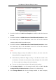
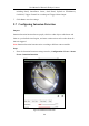
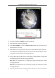
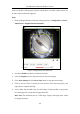
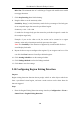
Table Of Contents
- Chapter 1 System Requirement
- Chapter 2 Network Connection
- Chapter 3 Access to the Network Camera
- Chapter 4 Live View
- Chapter 5 Network Camera Configuration
- Chapter 6 Network Settings
- Chapter 7 Video/Audio Settings
- Chapter 8 Configuring Image Parameters
- Chapter 9 Configuring Event Settings
- 9.1 Configuring Motion Detection
- 9.2 Configuring Video Tampering Alarm
- 9.3 Configuring Alarm Input
- 9.4 Configuring Alarm Output
- 9.5 Handling Exception
- 9.6 Configuring Audio Exception Detection
- 9.7 Configuring Intrusion Detection
- 9.8 Configuring Line Crossing Detection
- 9.9 Configuring Region Entrance Detection
- 9.10 Configuring Region Exiting Detection
- 9.11 Configuring Unattended Baggage Detection
- 9.12 Configuring Object Removal Detection
- Chapter 10 Storage Settings
- Chapter 11 People Counting
- Chapter 12 Heat Map
- Chapter 13 Intersection Analysis
- Chapter 14 Playback
- Chapter 15 Picture
- Chapter 16 Application
- Appendix

User Manual of Network Fisheye Camera
99
enter a pre-defined virtual region from the outside place, and some certain actions can
be taken when the alarm is triggered.
Steps:
1. Enter the Region Entrance Detection settings interface, Configuration > Event >
Smart Event > Region Entrance Detection.
Figure 9-12 Region Entrance Detection
2. Check the Enable checkbox to enable the function.
3. Select the Region from the drop-down list for detection settings.
4. Click Area Settings and click Draw Area button to start the area drawing.
5. Click on the live video to specify the four vertexes of the detection region, and
right click to complete drawing.
6. Set the Max. Size and Min. Size for valid targets. Targets smaller or larger than
the valid target size are not able to trigger detection.
Max. Size: The maximum size of a valid target. Targets with larger sizes would
not trigger detection.