
User Manual
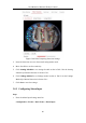
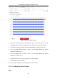
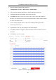
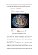
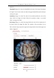
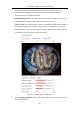
Table Of Contents
- Chapter 1 System Requirement
- Chapter 2 Network Connection
- Chapter 3 Access to the Network Camera
- Chapter 4 Live View
- Chapter 5 Network Camera Configuration
- 5.1 Configuring Local Parameters
- 5.2 Configuring System Settings
- 5.2.1 Viewing Basic Information
- 5.2.2 Time and DST Settings
- 5.2.3 RS-232 Settings
- 5.2.4 RS-485 Settings
- 5.2.5 Upgrade and Maintenance
- 5.2.6 Log Searching
- 5.2.7 System Service Settings
- 5.2.8 Authentication
- 5.2.9 IP Address Filter
- 5.2.10 Security Service
- 5.2.11 User Management
- 5.2.12 Open Source Software License
- 5.3 Configuring Network Settings
- 5.3.1 Configuring TCP/IP Settings
- 5.3.2 Configuring Port Settings
- 5.3.3 Configuring PPPoE Settings
- 5.3.4 Configuring DDNS Settings
- 5.3.5 Configuring NAT (Network Address Translation) Settings
- 5.3.6 Configuring SNMP Settings
- 5.3.7 Configuring FTP Settings
- 5.3.8 Email Settings
- 5.3.9 Configuring HTTPS Settings
- 5.3.10 Configuring QoS Settings
- 5.3.11 Configuring 802.1X Settings
- 5.4 Configuring Video and Audio Settings
- 5.5 Configuring Image Parameters
- 5.6 Configuring Event Settings
- 5.7 Configuring Heat Map
- Chapter 6 Storage Settings
- Chapter 7 Playback
- Chapter 8 Picture
- Chapter 9 Application
- Appendix

User Manual of Network Fisheye Camera
95
can be detected.
7. Click-and-drag the slider to set the detection sensitivity.
Sensitivity: Range [1 to 100]. The higher the value is, the more easily the line
crossing action can be detected.
8. You can click the Clear button to clear the pre-defined line.
9. Repeat the above steps to configure other lines. Up to 4 lines can be set. You can
click the Clear button to clear all pre-defined lines.
10. Set the arming schedule. Refer to Task 2: Set Arming Schedule for Motion
Detection in Section 5.6.1.
11. Set the linkage method. Refer to Task 3: Set Linkage Method for Motion
Detection in Section 5.6.1.
12. Click Save to save the settings.
5.6.7 Configuring Intrusion Detection
Purpose:
Intrusion detection function detects people, vehicle or other objects which enter and
loiter in a pre-defined virtual region, and some certain actions can be taken when the
alarm is triggered.
Note: Intrusion Detection is not supported when the decoding mode is hardware
decoding and the display mode is 4PTZ.
Steps:
1. Enter the Intrusion Detection settings interface:
Configuration > Event > Smart Event > Intrusion Detection
2. Check the checkbox of Enable to enable the function.
3. Select the region from the drop-down list for detection settings.
4. Click the Draw Area button to start the region drawing.
5. Click on the live video to specify the four vertexes of the detection region, and
right click to complete drawing.
6. Set the time threshold, detection sensitivity and object percentage for intrusion